
|
|
Forum Index : Microcontroller and PC projects : CMM Display problem
| Author | Message | ||||
Chrisk Senior Member Joined: 21/12/2014 Location: AustraliaPosts: 137 |
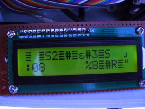
Hi Guys I am running MMBasic V4.5 on my Colour Maximite. I am using the LCD function to display data in a greenhouse. For some reason the display ends up jumbled as in the picture below. On loading of the program it works fine but fails after maybe a day or up to several days. There seems to be nothing regular about it. It's not a voltage problem. I have tried: purchasing and installing a new display installing additional filtering on the supply 10k pull ups, even though the manual says it does not require them. clearing the display before a write. The display still remains jumbled after receiving new data. I was going to use the LCD program that is in the library as another option but figured that this would have been put into the microprogram by Geoff. Any ideas and has anyone encountered this and what was the fix? Chris K 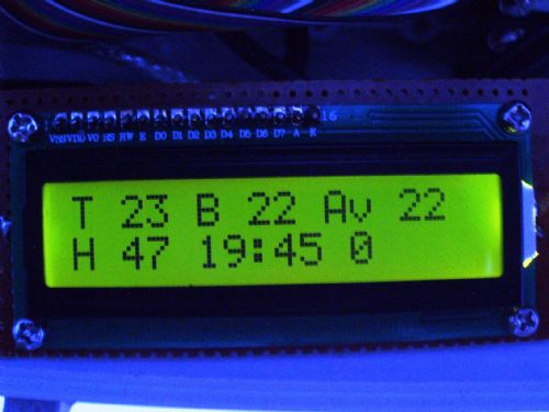
|
||||
bigmik Guru Joined: 20/06/2011 Location: AustraliaPosts: 2981 |
Hi Chris, Is this an I2C or SPI driven display or the parallel interface (using the MMBasic command?) I suspect the latter.. My guess would be that you `might' be powering it off 3v3 instead of 5v, if so these displays usually only run off 5v but some `may' appear to work off only 3v3.. A suggestion that might work would be to re-initialise the display just before every write. Can you add a small delay after every write? Have you tried a different brand of display module? Regards, Mick EDIT *** How far away from your MM is the display module? Mik Mick's uMite Stuff can be found >>> HERE (Kindly hosted by Dontronics) <<< |
||||
| robert.rozee Guru Joined: 31/12/2012 Location: New ZealandPosts: 2541 |
hi, what is the distance between the LCD module and the maximite? i see from the version 4.5 language manual that the maximite supports the command: LCD INIT d4, d5, d6, d7, rs, en to initialize a 16x2 LCD module. you may wish to try executing this command every hour or two within your code in case the module simply 'gets confused' at some point. initializing the module periodically should cause no harm. cheers, rob :-) |
||||
| Chrisk Senior Member Joined: 21/12/2014 Location: AustraliaPosts: 137 |
Hi Guys Thanks for the replies. Bigmik: I am using the parallel interface as shown in the 4.5 manual and have it running on 5V. I have a delay as shown in the lines below. Print " Sending LCD Data" LCD CLEAR Pause 100 LCD 1, 1, "T " + STR$(LT1)+ " B " + STR$(LT2) + " Av "+ STR$(LTA) + " "' Display Top, Bottom and Average Temps pause 100 LCD 2, 1, "H " + STR$(LHM) + " MC " + Format$(Miscnt,"%2g") + " " + MID$(Time$,1,5) ' Display Humidity Mist Count and Time on 2nd line The initialization is done early in the program. I had purchased two displays from different sources but their electrical characteristics may be the identical. ED: The display lead length is only about 300mm from the CMM Robert: I might have a go at initializing more often as I have a routine that runs every hour using the settick command. I'll let you know how it goes. Thanks Guys Chris K |
||||
| Chrisk Senior Member Joined: 21/12/2014 Location: AustraliaPosts: 137 |
Hi Guys Tried Robert's idea but attempting a re-initialize give the error message: Error: Already open. So it's back to the drawing board. Chris K  |
||||
| robert.rozee Guru Joined: 31/12/2012 Location: New ZealandPosts: 2541 |
looks like you need to issue an "LCD CLOSE" first. cheers, rob :-) |
||||
| isochronic Guru Joined: 21/01/2012 Location: AustraliaPosts: 689 |
I think Rob's reinitialisation idea is the way to go. The 16x2 LCD's have to be put into "nibble" mode to use the minimum connections. If the lcd resets and runs in byte-mode instead it will show gibberish as it interprets the nibbles as bytes. Sometimes 16x2 modules do not power-up cleanly unless the rise time is in a set range and so have to be reset with a defined sequence for reliable results, and then initialised after that. As an experiment I'd add bypass/tank capacitors to the lcd power supply, close to it, and see if it makes any difference. (ed) arrgh - was typing but rob got there first ! |
||||
| bigmik Guru Joined: 20/06/2011 Location: AustraliaPosts: 2981 |
Hi Chris, If all else fails you can try an I2C based LCD module.. It could also be due to the CMM's 3v3 levels and the LCD really wanting 5V drive levels.. It only needs one command being sent to get corrupted to upset the apple cart.. You might also try those 3v3-5V level translators ------> eBay example HERE!!!! <------ Although I feel as Rob suggests an LCD close followed (after a suitable delay) by a re-init either just before an update or every hour or so should kick it back into action. Regards, Mick Mick's uMite Stuff can be found >>> HERE (Kindly hosted by Dontronics) <<< |
||||
| robert.rozee Guru Joined: 31/12/2012 Location: New ZealandPosts: 2541 |
it does occur that you could possibly precede every write to the LCD with an LCD CLOSE and LCD INIT... command. although the close/init would also clear the screen. geoff: is there any reason why the LCD write command should not as standard send the 'set 4-bit mode' command every time it is called? while the extra nibbles sent may slow things down ever so slightly, the advantage of ensuring the write happens correctly may outweigh this. or perhaps an extended syntax: LCD line, pos, text$ [INIT] where the INIT flag uses the previously configured pins and doesn't clear the screen. cheers, rob :-) addendum: the command LCD CMD d1 [, d2 [, etc]] may well do the trick. if someone would care to look up the command sequence to set 4-bit mode? i'm just heading out the door right now. |
||||
| ajkw Senior Member Joined: 29/06/2011 Location: AustraliaPosts: 290 |
My thought/question is, what 'refresh' rate is Chris using? I have found if you flood these displays updating them too often, i.e. every program loop, you can get a garbled screen after a varied period. I only write to the screen when the information changes. Anthony. |
||||
| Chrisk Senior Member Joined: 21/12/2014 Location: AustraliaPosts: 137 |
Hi Guys I will try Robert's instruction 'LCD close' first being the simplest. Anthony: The display is only updated once every three minutes. Tried the bypass capacitors with 1000uF across the supply. I'll try Bigmiks idea of level translators after that if it is necessary. I would have thought that the 10k pullups would have helped but perhaps not enough. One would need to use a storage CRO to check the voltage levels. It happens so erratically that it's hard to determine when it fails. Will keep you informed Thanks again Guys Chris K |
||||
| MicroBlocks Guru Joined: 12/05/2012 Location: ThailandPosts: 2209 |
I had that exact same problem when i send a string of characters to a display, or using cursor commands followed by text. I solved it by sending one character at a time followed by a 25ms delay. If a display is slow then it will get confused recognizing a stop/start bit. It will then use the next low bit as a start bit which corrupts the data received and displayed. Adding the small delay will stretch the time between the stop bit and the start bit allowing the display to correctly decode the serial bitstream. If you have the possibility to use 2 stop bits instead of one it could also help. The slowness of the display also causes the problem you see when sending a command. Commands are being processed and during that time no new commands or data shuld be send. The display probably has a busy output pin that you can check, otherwise just use a small delay, around 50ms should be ok. I found that lots of problems with serial communication can be solved by adding some delays. Worked back in the days, controlling modems all the way to the current day where it works with WiFi/Wireless modules. If after adding delays the problem still occurs then it is time to go deeper. Microblocks. Build with logic. |
||||
| Chrisk Senior Member Joined: 21/12/2014 Location: AustraliaPosts: 137 |
Hi Guys As I mentioned I would try the re-initilization of the LCD every 1 hour. I found this worked and had only one occasion where the display was corrupted. Viewing after an hour or so and re-initialized it was again correct. I thought this was a way around the problem but I really wanted to fix it correctly. I took Big Mick's suggestion and purchased some level translators. So cheap I decided to purchase 10 small PCBs. Cost less than AU$5. Wired them in and thought this will finally fix it. After a day of corruption free running "bah humbug" corrupted again. So I have gone back to Robert's idea and re-initializing every hour. Thanks for your support Chris K |
||||
| The Back Shed's forum code is written, and hosted, in Australia. | © JAQ Software 2026 |
