
|
|
Forum Index : Microcontroller and PC projects : Has anyone made GPS Synchronised Clock?
| Page 1 of 2 |
|||||
| Author | Message | ||||
lew247 Guru Joined: 23/12/2015 Location: United KingdomPosts: 1709 |
I made the clock from here http://geoffg.net/GPS_Synchronised_Clock.html and originally I had a problem where the only gps module I could get was 9600 baud and not 4800 Geoff very kindly send me an updated hex code that worked at 9600 baud - Thanks Geoff, very few people would have done that. I however have a problem, I cannot "talk to it" using the computer I have tried a genuine rs232 port on the computer and an ttl/serial converter and neither will talk to it I need to not only change the DST settings from Australian time to UK time, but I need to change the clock pulse width (at least I think I do) I'm using one of the German UTS clock modules, and the stepper tries to move the 2nd hand once the gps gets a valid lock but it will not move. Anyone got any ideas how I could fix this problem and get it to communicate? It may be I blew par of the pic chip as I had the rs232 wired wrong to start with and the setup cable lite even with no power connected However once I fixed that the pic "seems to" work correctly, I'm getting the right combination of flashes on the led. |
||||
palcal Guru Joined: 12/10/2011 Location: AustraliaPosts: 2039 |
Have you wired the serial cable as per Geoff's web site, because the original wiring for the cable in The SC magazine was wrong, and maybe in the kit if you used one. I built this project and it worked fine. Paul. "It is better to be ignorant and ask a stupid question than to be plain Stupid and not ask at all" |
||||
| lew247 Guru Joined: 23/12/2015 Location: United KingdomPosts: 1709 |
Yes I used the info on Geoff's web site for the serial cable However the 1st time I stupidly got the pins backwards on the rs232 connector and the red light on the board lite without any power being applied I'm wondering if Its possible that I damaged the rs232 inputs on the pic chip is it possible to damage them and the pic still work as normal for all the other functions? I've ordered a new pic chip, and the genuine serial cable mentioned in the article So hopefully by this time next week it will be working perfectly :) |
||||
| robert.rozee Guru Joined: 31/12/2012 Location: New ZealandPosts: 2541 |
can you by chance provide the part number of the module you have used and/or a link? cheers, rob :-) |
||||
| lew247 Guru Joined: 23/12/2015 Location: United KingdomPosts: 1709 |
I got two and both are 9600 baud 1st one and 2nd one The clock module I got was this one This one Both GPS modules work great and lock on pretty fast indoors. |
||||
| robert.rozee Guru Joined: 31/12/2012 Location: New ZealandPosts: 2541 |
alas, neither resemble the modules i've been working with - part number VK16E purchased on ebay. as far as the serial connection is concerned for connecting a PC to the finished project, do yo have a USB to serial bridge avaialble, the variety that has TTL level signals? a popular one is here: http://www.ebay.com/itm/400565980256 CP2102 and CH340G based bridges are pretty much trouble-free, while PL2303 and FTDI based bridges can have various problems related to 'driver wars'. life is very much simpler with TTL levels, as you can just replace the 22k and 220r resistors with 1k resistors (or wire links) and leave out the 4k7 resistor. true RS-232 uses +/- 12v for signalling, although this may be only +/- 5v in some situations and/or the -ve voltage may be replaced with 0v. in all, the number of possible combinations makes it difficult to cater for with a simple voltage divider as in geoff's circuit. cheers, rob :-) addendum: it occurs to me that at the same time as going to TTL levels, you would need to get geoff to invert the Rx and Tx polarity within the firmware. the alternative would be to add in a couple of external inverters on a small piece of veroboard. |
||||
| lew247 Guru Joined: 23/12/2015 Location: United KingdomPosts: 1709 |
Edit Deleted as I fixed that problem |
||||
| lew247 Guru Joined: 23/12/2015 Location: United KingdomPosts: 1709 |
It's all working now apart from the clock hands will not move I am totally stumped. I've tried 2 clock modules, the second hand moves if I touch a 1.5v battery to the clock terminals so I know I've modified it properly. I cannot think of anything else that can be the problem, the board has all the 4 startup steps confirming on the led, the gps communicates and sends the correct signal when it gets a valid lock as the board led sends 4 flashes but the clock module will not move its hands I'm totally fed up with this now, I really wanted this to work and I cannot think what it could be thats wrong I've even gone into the menu and change the clock pulse to the maximum length Has anyone got one of these working that they no longer want and is willing to sell it? I'd like to buy a complete working one so I can see it working, and then maybe I can figure out whats wrong with mine. |
||||
| Frank N. Furter Guru Joined: 28/05/2012 Location: GermanyPosts: 1141 |
Hi lew247, can you tell me more from your modification? What hardware did you use for controlling your clockwork? Frank |
||||
| lew247 Guru Joined: 23/12/2015 Location: United KingdomPosts: 1709 |
Frank The "alternative board layout" on the website NOT THE ONE THAT CAME FROM SILICON CHIP in AU "seems to have a track in the wrong place" I had to cut the two track shown below (they control the pc talking to the pic chip) to be able to send commands to the program and then solder wires under the board making the tracks go where they were meant to go IE a lead from the bottom of the 22K resistor to pin 9 on the pic and another lead going from the bottom of the 22k resistor to the top of the 4k7 resistor 
I still have the problem that I have no voltage coming out of the pic on pins 17 and 18 which I guess means the timing circuit isn't working? but I already tried 2 crystals, both new so I have no idea what is wrong and basically I've given up |
||||
BobD Guru Joined: 07/12/2011 Location: AustraliaPosts: 935 |
The 1N4148 diode in the photo may not be soldered on the bottom leg. I don't have a circuit so I have no idea what effect that may have. |
||||
| Frank N. Furter Guru Joined: 28/05/2012 Location: GermanyPosts: 1141 |
Hi lew247, it seems that you have soldered the two 22pF capacitors on the oscillator in the wrong position! They are horizontal in Geoffs picture and they are vertical in your circuit! Your oscillator can't swing - your PIC can't work... Frank |
||||
| robert.rozee Guru Joined: 31/12/2012 Location: New ZealandPosts: 2541 |
it also looks like you have a 270k resistor in series with the output to the clock module (red-purple-yellow). this should be 270 ohm (red-yellow-brown). the 270k resistor will ensure the hands can not move! cheers, rob :-) |
||||
| cicciocb Regular Member Joined: 29/04/2014 Location: FrancePosts: 73 |
Maybe red-violet-brown for 270 ohm ?  |
||||
| robert.rozee Guru Joined: 31/12/2012 Location: New ZealandPosts: 2541 |
oops, you are right, 270 ohm is indeed red-violet-brown (red-purple-brown) 
cheers, rob :-) |
||||
| lew247 Guru Joined: 23/12/2015 Location: United KingdomPosts: 1709 |
The diode although it looks not soldered, is soldered underneath the board, however I will redo it when I get up in the morning However it is definitely working as the max756 is putting out the correct voltages. The resistor I actually measured it with a meter and it's 269 ohm I also measured the voltage coming out of pins 17 and 18 of the pic, but am getting no voltage output I "think" it's because the pins are only high for 40-56 mS and my meter might not be able to detect it, and I don't have an oscilloscope to check with The 22pf loading capacitors are actually in series with pins 12 and 13, with the other end of each capacitor going to ground, It looks like they are parallel in the photo, but the underneath of the board has the tracks going to the correct pins. The only thing I haven;t tried, and I am going to try when they arrive - I ordered them today, is 2 different 22pf capacitors, just in case I got sent the wrong values Other than that - I'm stumped! |
||||
| twofingers Guru Joined: 02/06/2014 Location: GermanyPosts: 1767 |
Are we talking about this resistor? That's astonishing! 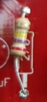
Are you a b s o l u t e l y sure? 
In addition I would inspect all solder points. Good luck! Regards Michael causality ≠ correlation ≠ coincidence |
||||
| robert.rozee Guru Joined: 31/12/2012 Location: New ZealandPosts: 2541 |
just for my own piece of mind, could you possibly check the resistor again? making sure that the clock module is not plugged in when you do the check. that multiplier band really looks like it is yellow, and not brown. cheers, rob :-) |
||||
| BobD Guru Joined: 07/12/2011 Location: AustraliaPosts: 935 |
rob In the picture below I have sampled the colour bands on each resistor with a colour picker. I then pasted each sample onto the image. You can see the effect. The band on the left hand resistor did vary a bit from light yellow to a mustard colour depending where the sample was. bob edit: I updated the image to show the yellow range. 
|
||||
| Frank N. Furter Guru Joined: 28/05/2012 Location: GermanyPosts: 1141 |
Hi, please check your 22pF capacitors again. The 22pF are in a different direction in this photo from Geoff: 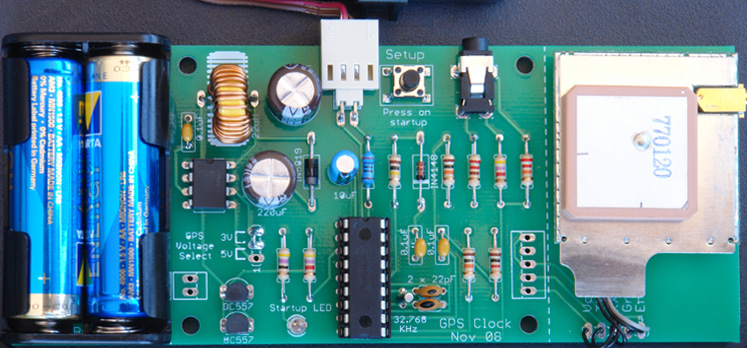
They are not good to see in your photo - they are cut through in the middle in your photo at the under edge: 
Frank |
||||
| Page 1 of 2 |
|||||
| The Back Shed's forum code is written, and hosted, in Australia. | © JAQ Software 2026 |
