
|
|
Forum Index : Microcontroller and PC projects : Problem with ILI9341 64 PIN MM+ and Touch
| Author | Message | ||||
| atmega8 Guru Joined: 19/11/2013 Location: GermanyPosts: 724 |
Hello Geoff, spent some hours on getting this running. Connected the Touch related PINs to pin 64 and 63. OPTION LCDPANEL ILI9341, L, 60, 61, 62, and option touch 63, 64. Display is connected to + 5 V and GND. Display output ok, but no Interrupt generation when Touch event. OPTION TOUCH 31, 32 works ! Only get Error: > gui calibrate Warning: Inaccurate calibration Is it not possible to use PIN 64, 63 ? Documentation says not, that this is "forbidden". Can this be an issue because of overlapping SSD1963 PIN'S (60-64 and 1-3)? Or maybe because off different 5V tolerating PIN's? Whatever it is, i think it is be worth to put it into the documentation, to prevent others from frustrations .. 
THX, ATMEGA8 |
||||
palcal Guru Joined: 12/10/2011 Location: AustraliaPosts: 1989 |
If you are getting the message of Inaccurate calibration you will have to calibrate again. Use a fine stylus to touch the cross and hold until the next target appears. Paul. "It is better to be ignorant and ask a stupid question than to be plain Stupid and not ask at all" |
||||
| atmega8 Guru Joined: 19/11/2013 Location: GermanyPosts: 724 |
Thank you, but the Primary Problem is the not working Pins 64,63... Can someone Test / confirm this? Maybe this is a Bug? |
||||
| atmega8 Guru Joined: 19/11/2013 Location: GermanyPosts: 724 |
I checked PIN 64/63 with an ISR. No Problem so far.. Calibration successful with a small stick. I think a bug gets more and more possible.. SETPIN 64, INTH, RInt, pulldown ' setup an interrupt when RA goes high SETPIN 63, INTH, RInt2, pulldown ' setup an interrupt when RA goes high DO pause 1000 print "Main" LOOP SUB RInt ' Interrupt to decode the encoder output print "Interrupt pin 64" END SUB SUB RInt2 ' Interrupt to decode the encoder output print "Interrupt pin 63" END SUB |
||||
| atmega8 Guru Joined: 19/11/2013 Location: GermanyPosts: 724 |
Something more: With Touch PIN 64/63 GUI Interrupts don't work. But gui calibration was working! Strange, isn't it? Go to sleep now, good night. |
||||
disco4now Guru Joined: 18/12/2014 Location: AustraliaPosts: 1000 |
There is discussion here about whether ILI9341 should be powered at 5V I see only one of 63,64 is 5v tolerant, but both 31,32 are 5v. You could try 64,63 in lieu of 63,64 to see if this is anything to do with it. Regards Gerry Latest F4 Latest H7 FotS |
||||
| atmega8 Guru Joined: 19/11/2013 Location: GermanyPosts: 724 |
This discussion is mainly about Background Illumination. The ( my ??) Problem persists. For my understandig ist doesn't matter, if the IRQ Pin is 5 Volt Tolerant or not. In both cases the Display should be able to generate an Interrupt, to Service the touch Event. Because i don't have the Equipment (Oszillograph/ Logic Analyzer etc.) i am stuck in this Situation. So any Support would be great. THX |
||||
| Geoffg Guru Joined: 06/06/2011 Location: AustraliaPosts: 3285 |
There is no reason why touch will not work with pins 64 and 63. In this respect all I/O pins are equal. At this time I don't have the spare time available to setup a test system to prove this but I am sure that you have not found a bug. The most likely cause is that something is wrong with your setup or code. Geoff Geoff Graham - http://geoffg.net |
||||
| atmega8 Guru Joined: 19/11/2013 Location: GermanyPosts: 724 |
Hi Geoff, the identical/same code works with other Pins but not with pin 64 and 63. I tested the Pins 64 and 63 / Interrupt with the code beneath. So HW seems to be ok. SETPIN 64, INTH, RInt, pulldown ' setup an interrupt when RA goes high SETPIN 63, INTH, RInt2, pulldown ' setup an interrupt when RA goes high DO pause 1000 print "Main" LOOP SUB RInt ' Interrupt to decode the encoder output print "Interrupt pin 64" END SUB SUB RInt2 ' Interrupt to decode the encoder output print "Interrupt pin 63" END SUB THX for your engagement |
||||
| matherp Guru Joined: 11/12/2012 Location: United KingdomPosts: 10240 |
I've just tested ILI9341, MM+ (64-pin). Option touch 63,64 and option touch 64,64 both work fine and calibrate perfectly. 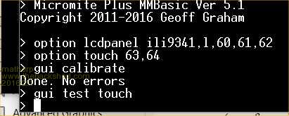
Check for things like a short between the pins on the uP |
||||
| atmega8 Guru Joined: 19/11/2013 Location: GermanyPosts: 724 |
Hi Peter, thank you very much for testing this Setup. I have tested the Pins with this little Interrupt Routine above. Next step will be to use another 64 Pin Controller. In the next days i will receive a new sample from microchip. The Interrupt will be generated from the LCD Panel, correct? Do you know how MM+ will set the Trigger Level / use Pullups/downs? So i can investigate deeper. Tommorow i will have a Rigol Oscillograph on site. Hope to find some time. Stay tuned ;-) Thank you very much. |
||||
| matherp Guru Joined: 11/12/2012 Location: United KingdomPosts: 10240 |
XPT2046 chip generates a logic level signal on the T_IRQ pin. Disconnect this from the Micromite and connect direct to a multimeter with the other lead on gnd. You should see a 3.3V level. Touch the screen lightly and the level will drop to GND. This works even if touch hasn't been configured in the Micromite and even if all other touch signals are disconnected (T_DO, T_DIN, T_CS, T_CLK) |
||||
| atmega8 Guru Joined: 19/11/2013 Location: GermanyPosts: 724 |
Ok, my Interrupt ISR tested the rising Signal (INTH). Maybe the IRQ PIN has a Problem with INTL ?! Strange, but everything is possible, as Murphy said ;-) I will read the datasheet of the XPT2ß046, check this in the late evening and give Feedback. Thank you so much |
||||
| atmega8 Guru Joined: 19/11/2013 Location: GermanyPosts: 724 |
After soldering a new PIC controller onto the board, all problems vanished. Again, it was the BUG in front of the Monitor 
THX |
||||
| The Back Shed's forum code is written, and hosted, in Australia. | © JAQ Software 2025 |
