
|
|
Forum Index : Microcontroller and PC projects : uMite (mx170) with USB/programmer DIP28
| Page 1 of 2 |
|||||
| Author | Message | ||||
| MicroBlocks Guru Joined: 12/05/2012 Location: ThailandPosts: 2209 |
I have just finished the design of a uMite MX170 together with a USB-Serial-Programmer all on a pcb the size of a DIP-28/600mil. I think (hope  ) that this would be the simplest to use uMite because of its integrated USB to Serial chip. The uMite can also be programmed without the need of an external programmer. ) that this would be the simplest to use uMite because of its integrated USB to Serial chip. The uMite can also be programmed without the need of an external programmer.
It gets power through the USB. The console of the uMite works right away, so you can start programming it with a terminal or MMEdit. If you want to update the uMite firmware it is just adding a jumper between pin 1 and 3 of the ICSP connector. The ICSP is there in case the firmware of the USB-Serial needs to be updated and to bring out some pins of the PIC16F1455 that might be useful when you are hacking it. :) Schematic: 
PCB: 
The estimated price fully assembled will be around 14.95USD. I expect these to be available beginning of march. Comments/suggestions are welcome! Microblocks. Build with logic. |
||||
| WhiteWizzard Guru Joined: 05/04/2013 Location: United KingdomPosts: 2991 |
A really well thought out module 
Personally I would have also added one of the tiny tactile buttons (for reset). This is NOT a criticism; just some feedback. Also would put in a PTC (in USB +5v line) just in case! I will be interested in ordering one as soon as they are available 
WW |
||||
| MicroBlocks Guru Joined: 12/05/2012 Location: ThailandPosts: 2209 |
First, I am having problem sourcing the right tiny smd tactile button. Second, There is a function in the software of the pic16f1455 to reset the MX17. It can be either a DTR from the terminal (MMEdit), or a key combination (currently CTRL+R) over the console. Third, The reset pin is also right next to the gnd pin so shorting these will give a reset. No worries about getting a dirty reset as the supervisor chip will clean that up. Having the above three 'reasons' i thought i could get away without a reset button. :) But i understand the reason as i also prefer to have one. A PTC is a good addition. I will do that. Might as well add a diode too. Microblocks. Build with logic. |
||||
| viscomjim Guru Joined: 08/01/2014 Location: United StatesPosts: 925 |
This is VERY COOL!!!! Nice job. I will definitely want a couple of those. Great work!! |
||||
| MicroBlocks Guru Joined: 12/05/2012 Location: ThailandPosts: 2209 |
Anyone has a suggestion for a reliable PTC? It should allow for about 200-250ma. Microblocks. Build with logic. |
||||
| Zonker Guru Joined: 18/08/2012 Location: United StatesPosts: 772 |
Nice PCB Jean..! I really like the 28 pin socket format.. I have several here left from the prototype run and use them a lot, as they are small and fit nicely onto the smaller vector boards... I used the FTDI IC for USB (genuine) and during firmware programming of the MM, I also went into the FTDI chip and changed the settings to ask the USB controller to set the USP power to allow 300ma... It had separate reg's, one for the MM cpu, and the other was for the board user.. with a small heat spreader. I was able to get sustained 200ma (sometimes more for awhile)... If you overheated the reg, it would shut you down, but the MM would still work OK... If you suddenly ask for more than that, the USB controller would bitch, and shut down the whole thing... I never seemed to trip the PTC part... Maybe if a catastrophic hardware failure happened while you had it powered from a wall wart.. Don't know... I think i used 250ma PTC's... (will check).. Anyway, setup up like this, the board would power the whole project on the vector board from the USB (with LCD displays running) and a few project IC's with it... Is there a way for your USB IC the do the same thing..?? How much current can you draw from the power pins..? Thanks for any feedback...! P.S. I would be interested in a few of these fine PCB's.. I love the "on board" programmer..!! |
||||
| MicroBlocks Guru Joined: 12/05/2012 Location: ThailandPosts: 2209 |
Ihe voltage regulator is a 250ma type and has all the safety features build in against shorts, overheating etc. This is however only for the 3.3v. The 5v is a direct connection with the USB. As most USB ports are protected against an overload i did not include a PTC as it would just copy that safety feature. The same is for instance placing a diode to protect the USB against external power. The diode would drop the voltage about 0.6v lower than the voltage that comes out of the USB to about 3.9v as most USB ports provide about 4.5 volts to start with. It gets complicated quickly to protect against every fault. I did look into increasing the load the chip can ask from the USB, did not get it to work.... yet. Microblocks. Build with logic. |
||||
| MicroBlocks Guru Joined: 12/05/2012 Location: ThailandPosts: 2209 |
I just send it to the PCB manufacturer.
Changed the layout a bit so all parts align. This will make placing them easier. I also added a jumper to choose between USB power or external power. These two pads can also be used to add a PTC, a diode, a switch or be used as two connections to easily measure the current being used. 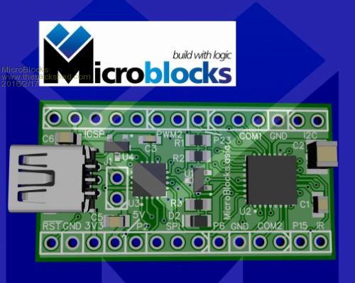
Now wait....... Microblocks. Build with logic. |
||||
| MicroBlocks Guru Joined: 12/05/2012 Location: ThailandPosts: 2209 |
Got some stuff in the mail today. Still need to finish my little manual pick&place jig to populate those boards. I plan to do them while they are still panelized, so about 10 pieces per time. Microblocks. Build with logic. |
||||
| isochronic Guru Joined: 21/01/2012 Location: AustraliaPosts: 689 |
Looks good TZ! A question, are the pic icsp pins accessable, ie can the pic be loaded and run with other firmware ? |
||||
| MicroBlocks Guru Joined: 12/05/2012 Location: ThailandPosts: 2209 |
The pic can be loaded and programmed with the onboard USB/Serial converter. It also contains a programmer! (It is the small chip (pic16f1455) on the left in the picture) The pcb's purpose is to be as user friendly as possible and work with readymade firmwares. For updating no other equipment is necessary as everything is done through the USB port. When used as a uMite you loose two PWM pins as they are directly connected to the pic16f1455. For other uses it all depends on how you map the pins. The silkscreen is also as a uMite. Check the schematic for full details. If you need the debugging capabilities of a PicKit3 then you can use one of the other PGD/PGC pins (there are three sets available). However the MCLR pin of the pic32 is not directly available, but if really needed can be accessed through a via or the supervisory chip. I am also busy with a version in a DIP40 that carries a 44 pin MX170. Microblocks. Build with logic. |
||||
| robert.rozee Guru Joined: 31/12/2012 Location: New ZealandPosts: 2541 |
hi, i really do like the concept - very Arduino Nano like. the one concern i have, however, is potential confusion over the mmbasic pin numbering not matching the module pin numbering. have you considered connecting the PIC32 pins 1-1, 2-2, etc, while creating a seperate smaller 3-pin connector (PGC, PGD, MCLR only) for the PIC16's ICSP port? this could work well if you switched to a SSOP package for the PIC32, very much simplifying the routing. cheers, rob :-) addendum: can the PIC16 not hi-Z the PGC and PGD pins running to the PIC32 when not in ascii-ICSP mode? this would allow these pins to retain their normal mmbasic functions. |
||||
| MicroBlocks Guru Joined: 12/05/2012 Location: ThailandPosts: 2209 |
Rob, Thanks for the comments. Something to consider as i would like it to be as easy to use as possible. I am not sure what you mean with 'not hi-Z the PGC and PGD' pins. When it is not in ascii-ICSP mode i switch those pins to an input (Tri-State) by setting the register TRISA bits to a 1. I routed it so that pins that work together like COM/PWM/I2c are grouped and will be easier to wire up. The QFN also has different pin numbers then a dip/ssop/soic so i used the Pxx on the silkscreen. Mick also just remarked that the icsp for the picf1455 does not have to be a full icsp connector, making room for the other pins. Great minds think alike. :) Microblocks. Build with logic. |
||||
| robert.rozee Guru Joined: 31/12/2012 Location: New ZealandPosts: 2541 |
i was referring to your earlier comment "When used as a uMite you loose two PWM pins as they are directly connected to the pic16f1455". i assumed the two pins you were talking about were the PGC and PGD pins. as to the pin numbering/grouping, there are certainly good arguments on both sides. grouping pins together by function makes sense in terms of not having wires goung all over the place when connecting an accessory, particularly for new users. the ideal solution would be a 'special' build of micromite basic with then pin numbers swapped around to match the board layout. but then that would also require a modified manual with all the pin numbers changed round. cheers, rob :-) |
||||
| MicroBlocks Guru Joined: 12/05/2012 Location: ThailandPosts: 2209 |
Today spent some time to make a reference 'card' for this module. @Panky, I liked what you did with White Wizard's module and i used the same colors as it really enhances the clarity. I would like to ask your permission to use that style. Here is what i have now: 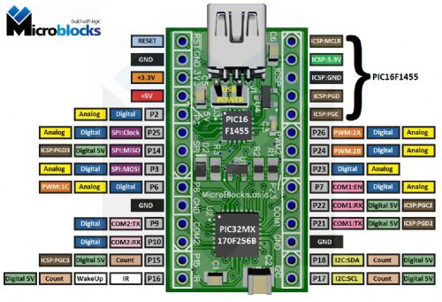
I also added the pin numbers that are used in MMBasic as on this module the pins are grouped per functionality. Microblocks. Build with logic. |
||||
| viscomjim Guru Joined: 08/01/2014 Location: United StatesPosts: 925 |
This is a very cool little board MicroBlocks!!! Are you making these yourself with the skillet method? Those two tiny pic packages really let you cram a lot on a small board. Will you be selling these? Great Job!!! |
||||
| MicroBlocks Guru Joined: 12/05/2012 Location: ThailandPosts: 2209 |
Thanks! I use a little hotplate (same principle) and a hot air station. I will be selling these once i get my assembly going. Currently just moved to a new city and lots of stuff still in boxes. Microblocks. Build with logic. |
||||
CircuitGizmos Guru Joined: 08/09/2011 Location: United StatesPosts: 1427 |
I ended up using "uM" as a designation when I made the pin-out graphic for the Arduino-like CGMICROBOARD2 graphic. That was to make sure that there was a noticeable difference between the "D" designation for Arduino and the Micromite pin designation. Like this: 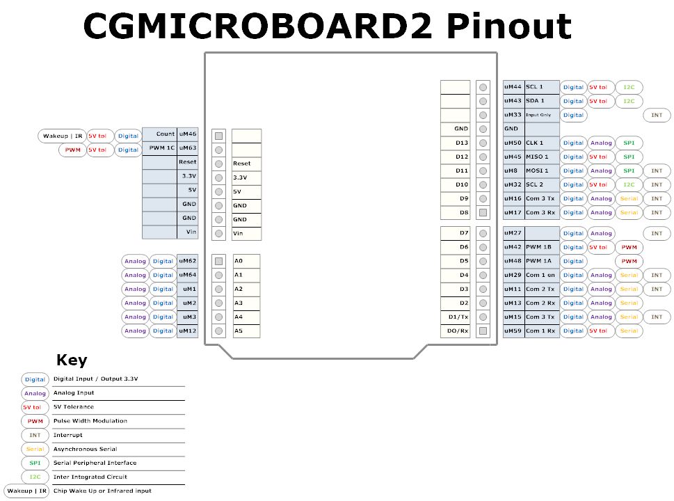
http://circuitgizmos.com/wp-content/uploads/2015/11/cgmicroboard2pinout.gif Micromites and Maximites! - Beginning Maximite |
||||
| MicroBlocks Guru Joined: 12/05/2012 Location: ThailandPosts: 2209 |
Yes i saw that already in your other topic about reference cards. This module however does not have an arduino like footprint as it is not an arduino and not designed to interface with arduino shields. I personally think it is just a gigantic waste of pcb space and also results in larger then necessary enclosures. The sooner this arduino footprint design failure (with the stupid off grid pins) gets out of existence the better. Microblocks. Build with logic. |
||||
| isochronic Guru Joined: 21/01/2012 Location: AustraliaPosts: 689 |
Right on !! It may have been a good idea at the start but now it is just another failed marketing leverage |
||||
| Page 1 of 2 |
|||||
| The Back Shed's forum code is written, and hosted, in Australia. | © JAQ Software 2026 |
