
|
|
Forum Index : Microcontroller and PC projects : Driving 7 segment displays
| Page 1 of 2 |
|||||
| Author | Message | ||||
Herry Senior Member Joined: 31/05/2014 Location: AustraliaPosts: 261 |
Hi For a relatively simple project, I would like to drive 3 X 7 segment displays from the Micromite. Currently I am using a 2 line LCD display connected as per manual. Not using this will free up pins 2,3,4,5. Other unused pins are 16,17,18,25,10,9,7,6. I would like to display up to 3 digits from a variable in the program I've written (Max figure would be 120). As readers of my occasional posts will attest I am a rank beginner who sometimes does not understand stuff right in front of his nose! I am wondering if use can be made of the MMBasic command LCD... Senior?! �Whatever it says, I'm a complete and utter beginner... |
||||
CircuitGizmos Guru Joined: 08/09/2011 Location: United StatesPosts: 1427 |
The LCD command's pin wigglings are not compatible with 7-segment displays, so you are unfortunately not going to be able to hook up the 7-segment LEDs and use the LCD command. But driving 7 segment displays isn't too difficult. Take a look at this to start: http://www.electronics-tutorials.ws/blog/7-segment-display-tutorial.html That covers the basics of one 7-seg display. To do three you set up the common connections to each 7-seg and share the segment lines. You can write code to cycle through and display each number (pattern) one at a time on each 7-seg display. Doing this fast enough makes it look like all three are lit at the same time, but you are really lighting them sequentially. 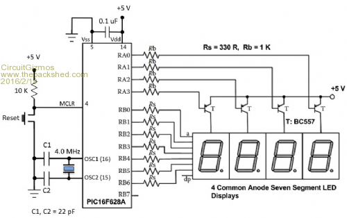
Micromites and Maximites! - Beginning Maximite |
||||
| Herry Senior Member Joined: 31/05/2014 Location: AustraliaPosts: 261 |
Thanks. Must I use a separate chip and how to integrate it so that it reads/displays from an MMBasic variable? Senior?! �Whatever it says, I'm a complete and utter beginner... |
||||
| CircuitGizmos Guru Joined: 08/09/2011 Location: United StatesPosts: 1427 |
The PIC16F628A in the sample schematic is a microcontroller just as the MicroMite is. You can connect the 7-seg displays like the schematic shows, using pins from the MicroMite instead. You would have three displays rather than the 4 shown. The schematic is for Common Anode displays. Similar schematics can be found for Common Anode 7-seg displays. As a reference in the diagram above selecting one of the displays is done by selecting one common anode line (RA0 to RA3) and setting the RB0-6 lines to illuminate the correct pattern of LEDs. Each 7-seg is individually selected and the pattern for that number is output on the RA lines. Again your lines on the uM wouldn't have the RA and RB designations, but would perform the same functions. Micromites and Maximites! - Beginning Maximite |
||||
palcal Guru Joined: 12/10/2011 Location: AustraliaPosts: 2039 |
Hi Herry, Look up '7 segment display driver' it means another chip by it makes it a lot easier. Paul. "It is better to be ignorant and ask a stupid question than to be plain Stupid and not ask at all" |
||||
| Herry Senior Member Joined: 31/05/2014 Location: AustraliaPosts: 261 |
OK, but presumably I'll need some nifty programming to read my numeric variable onto the displays? (I admit to being a bit spoiled by the ease of the MMBasic LCD command!) Senior?! �Whatever it says, I'm a complete and utter beginner... |
||||
Grogster Admin Group Joined: 31/12/2012 Location: New ZealandPosts: 9985 |
Have you seen matherp's thread here? All the hard work done for you, and the modules are dead cheap. You would just not use the 4th digit, or use digits 2-4 and not use digit 1. There is also the SPI 595 method - I use a 595 LED display in this thread and it only uses two MM pins(the SPI port) - four wires including power. The displays can be had on eBay for next to nothing. Smoke makes things work. When the smoke gets out, it stops! |
||||
| Herry Senior Member Joined: 31/05/2014 Location: AustraliaPosts: 261 |
Sorry to be so thick but I suspect lots of that code has to do with the time format and count. I am having problems relating it all to my need to display a simple mmbasic integer variable, which may be from 0 to say 120. No decimal point required. I have done a lot of searching for this and the examples are a bit over my head at the moment, and far longer and more complicated than I hoped. Senior?! �Whatever it says, I'm a complete and utter beginner... |
||||
| Grogster Admin Group Joined: 31/12/2012 Location: New ZealandPosts: 9985 |
Fair comment - matherp code is pretty advanced. Have a look at my edit to my post above about the 595 LED displays. These only need two wires(the SPI port), are cheap, and the code to drive them is much, much simpler... Smoke makes things work. When the smoke gets out, it stops! |
||||
| Grogster Admin Group Joined: 31/12/2012 Location: New ZealandPosts: 9985 |
You can also get those 595 displays in a nice bezel ready for plonking into a front panel. These are the ones I have used, and they look great. A bit more expensive, but it is probably worth it if you want it all packaged up ready to go. Smoke makes things work. When the smoke gets out, it stops! |
||||
TassyJim Guru Joined: 07/08/2011 Location: AustraliaPosts: 6543 |
If you want to drive your 7 segment displays directly, you need 7 pins for the segments and one pin for each digit as well as driving transistors for the digits. In code, you have to convert each digit into 7 segment, output the data, turn the digit on briefly, turn it of and proceed to the next digit. All this is relatively easy but you program will spend all it's time displaying the digits and this makes doing anything else tricky. The modules that Grogster referred to solve a lot of the problems Once you have the module, a simple subroutine can output the display data very easily. At less than $2 posted it is worth the wait. Jim VK7JH MMedit |
||||
OA47 Guru Joined: 11/04/2012 Location: AustraliaPosts: 1050 |
Herry some time ago i posted some code that had a 28 pin micromite directly attached to a 2-1/2 digit LED display (via some resistors) to read and display temperature from 0-199 degrees. This used the minimal amount of hardware and each segment of the LED was controlled by one pin of the micromite. http://www.thebackshed.com/forum/forum_posts.asp?TID=7935&PN=18&TPN=1 May be of some use GM |
||||
| Herry Senior Member Joined: 31/05/2014 Location: AustraliaPosts: 261 |
Again thanks all. Fed up, I decided to go right back to basics and consider one segment at a time, eg 0 is segments a-f and 8 is segments a to g. Obviously I needed a matrix. At that point fell asleep after lunchtime red (it's Saturday)! My scribblings were remarkably like that shown by Microblocks but I was then puzzled afresh by the 3 digits shown on that illo at the end of that thread. I suppose I suspected that there must be a driver chip that would do all that for me from firmware... I'll lash something up shortly if that search fails! Senior?! �Whatever it says, I'm a complete and utter beginner... |
||||
| Zonker Guru Joined: 18/08/2012 Location: United StatesPosts: 772 |
Morning Herry... I tried this earlier with a 4 digit clock display and just directly drove the LED with the MM pins... Probably not the best thing to do with the MM pins, but it did work ok... ' LED Display Test Program ' Init Segment Drive Pins For x=2 To 7: Pin(x)=0: SetPin x, dout: Next x For x=9 To 10: Pin(x)=0: SetPin x, dout: Next x ' Init Digit Drive Pins For x=23 To 26: Pin(x)=1: SetPin x, dout: Next x ' Engage scan and inc routines (timer intrupts) SetTick 8, scan, 1 ' timer 1 SetTick 10, inc_digits, 2 ' timer 2 Do: Loop Sub inc_digits digit4=digit4+1 If digit4>=10 Then digit4=0: digit3=digit3+1 If digit3>=10 Then digit3=0: digit2=digit2+1 If digit2>=10 Then digit2=0: digit1=digit1+1 If digit1>=10 Then digit4=0: digit3=0: digit2=0: digit1=0 End Sub ' Subroutine to scan the 4 digit display Sub scan If scandigit>=5 Then scandigit=1 If scandigit=1 Then decode (digit1): Pin(26)=0 If scandigit=2 Then decode (digit2): Pin(25)=0 If scandigit=3 Then decode (digit3): Pin(24)=0 If scandigit=4 Then decode (digit4): Pin(23)=0 scandigit=scandigit+1 Pause 2 For x=23 To 26: Pin(x)=1: Next x ' turn off all digits End Sub Sub decode(val) If val=1 Then Port(2,6,9,2)=&B00000110 If val=2 Then Port(2,6,9,2)=&B01011011 If val=3 Then Port(2,6,9,2)=&B01001111 If val=4 Then Port(2,6,9,2)=&B01100110 If val=5 Then Port(2,6,9,2)=&B01101101 If val=6 Then Port(2,6,9,2)=&B01111101 If val=7 Then Port(2,6,9,2)=&B00000111 If val=8 Then Port(2,6,9,2)=&B01111111 If val=9 Then Port(2,6,9,2)=&B01100111 If val=0 Then Port(2,6,9,2)=&B00111111 End Sub I used this LED digit display... 2016-02-20_131728_Lite-On_4_Digit_Clock_Display_S_110_C4727JR.pdf This company also makes "self scanning" units that you send bit patterns to that take care of the scanning task for you... 2016-02-20_132127_Serial_LED_4_Digit_Display_Module_LTM-8328PKR-04.pdf Grab one and get some play time going... 
|
||||
| Herry Senior Member Joined: 31/05/2014 Location: AustraliaPosts: 261 |
Morning... I wonder why you say that? Does that stress the Mirochip? Would it be better to use buffer transistors? Senior?! �Whatever it says, I'm a complete and utter beginner... |
||||
| Herry Senior Member Joined: 31/05/2014 Location: AustraliaPosts: 261 |
Further thoughts. With a basic requirement of having seven pins dedicated to each digit (assuming no decimal required, which it isn't for my project), the thought of 3 digits suggests 21 dedicated pins. But my thinking is now along the lines of switching the anodes by the seven segments, but choosing the cathodes (per digit) using three pins. So a total of 10 would do it. How does that sound? Senior?! �Whatever it says, I'm a complete and utter beginner... |
||||
| TassyJim Guru Joined: 07/08/2011 Location: AustraliaPosts: 6543 |
That is the method used in the second post of this thread. It is called multiplexing and works well but you then have to continually switch each digit on in turn. This takes up processing time and makes any other things your program is doing more complex. If you only want a 'one' in the first digit and no decimal point, you can use 7 + 7 + 2 = 16 pins without having to multiplex. Jim VK7JH MMedit |
||||
| OA47 Guru Joined: 11/04/2012 Location: AustraliaPosts: 1050 |
Jim, for the 100's digit you only need one output pin. 7 + 7 + 1 = 15 GM |
||||
| TassyJim Guru Joined: 07/08/2011 Location: AustraliaPosts: 6543 |
Driving two segments directly from the 'mite is likely to overload the pin. With low current devices that is OK but some will result in a dim 'one' I was playing safe. Jim VK7JH MMedit |
||||
| matherp Guru Joined: 11/12/2012 Location: United KingdomPosts: 11606 |
Here is a variant of the approach in Zonker's code. This allows completely free setting of pins and supports both common anode and common cathode displays of 1-4 digits. It also includes a "complete" ascii character map although some characters (e.g. "m") are obviously not able to be approximated. To display anything just put the required string into the variable out$ so out$="123" will display as expected. Use str$(num, no_of_digits) to convert a number one or more decimal points can be placed anywhere on the display by setting a non-zero value in the relevant position in the dp% array. Hopefully the setup for a specific display is easy to understand from the comments in the code option explicit option default none ' ' first define the display type and its connections, The pin connections must be in the order as commented ' The code assumes that for a common anode display the digit drives are connected via a PNP transistor ' The code assumes that for a common cathode display the digit drives are connected via a NPN transistor ' The segment connections can be made directly to the Micromite pins but adding a current limiting resistor is best practice ' const ndigits%=3 'set the number of digits in the display const on%=0 'set to 1 if common cathode display const off%=1 'set to 0 if common cathode display const all_on%=0 'set to 255 if common cathode display const all_off%=255 'set to 0 if common cathode display ' ' pin assignments ' const seg_a%=2 'top const seg_b%=3 'upper right const seg_c%=4 'lower right const seg_d%=5 'bottom const seg_e%=35 'lower left const seg_f%=36 'upper left const seg_g%=37 'centre const seg_dp%=38 'decimal point dim drivepins%(3)=(12,13,32,0)'left, midleft, midright,right ' dim dpos%=0, lastpos%=0, out$ length ndigits%, dp%(ndigits%-1) dim digittosegment%(126) ' array to hold the character bitmaps ' ' set the bit patterns for all "displayable" ascii characters ' DATA &B1111110 ' 0 DATA &B0110000 ' 1 DATA &B1101101 ' 2 DATA &B1111001 ' 3 DATA &B0110011 ' 4 DATA &B1011011 ' 5 DATA &B1011111 ' 6 DATA &B1110000 ' 7 DATA &B1111111 ' 8 DATA &B1111011 ' 9 DATA &B1110111 ' 10 "A" DATA &B0011111 ' 11 "B" DATA &B1001110 ' 12 "C" DATA &B0111101 ' 13 "D" DATA &B1001111 ' 14 "E" DATA &B1000111 ' 15 "F" DATA &B0000000 ' 16 NO DISPLAY DATA &B0000000 ' 17 NO DISPLAY DATA &B0000000 ' 18 NO DISPLAY DATA &B0000000 ' 19 NO DISPLAY DATA &B0000000 ' 20 NO DISPLAY DATA &B0000000 ' 21 NO DISPLAY DATA &B0000000 ' 22 NO DISPLAY DATA &B0000000 ' 23 NO DISPLAY DATA &B0000000 ' 24 NO DISPLAY DATA &B0000000 ' 25 NO DISPLAY DATA &B0000000 ' 26 NO DISPLAY DATA &B0000000 ' 27 NO DISPLAY DATA &B0000000 ' 28 NO DISPLAY DATA &B0000000 ' 29 NO DISPLAY DATA &B0000000 ' 30 NO DISPLAY DATA &B0000000 ' 31 NO DISPLAY DATA &B0000000 ' 32 ' ' DATA &B0000000 ' 33 '!' NO DISPLAY DATA &B0100010 ' 34 '"' DATA &B0000000 ' 35 '#' NO DISPLAY DATA &B0000000 ' 36 '$' NO DISPLAY DATA &B0000000 ' 37 '%' NO DISPLAY DATA &B0000000 ' 38 '&' NO DISPLAY DATA &B0100000 ' 39 ''' DATA &B1001110 ' 40 '(' DATA &B1111000 ' 41 ')' DATA &B0000000 ' 42 '*' NO DISPLAY DATA &B0000000 ' 43 '+' NO DISPLAY DATA &B0000100 ' 44 ',' DATA &B0000001 ' 45 '-' DATA &B0000000 ' 46 '.' NO DISPLAY DATA &B0000000 ' 47 '/' NO DISPLAY DATA &B1111110 ' 48 '0' DATA &B0110000 ' 49 '1' DATA &B1101101 ' 50 '2' DATA &B1111001 ' 51 '3' DATA &B0110011 ' 52 '4' DATA &B1011011 ' 53 '5' DATA &B1011111 ' 54 '6' DATA &B1110000 ' 55 '7' DATA &B1111111 ' 56 '8' DATA &B1111011 ' 57 '9' DATA &B0000000 ' 58 ':' NO DISPLAY DATA &B0000000 ' 59 ';' NO DISPLAY DATA &B0000000 ' 60 '<' NO DISPLAY DATA &B0000000 ' 61 '=' NO DISPLAY DATA &B0000000 ' 62 '>' NO DISPLAY DATA &B0000000 ' 63 '?' NO DISPLAY DATA &B0000000 ' 64 '@' NO DISPLAY DATA &B1110111 ' 65 'A' DATA &B0011111 ' 66 'B' DATA &B1001110 ' 67 'C' DATA &B0111101 ' 68 'D' DATA &B1001111 ' 69 'E' DATA &B1000111 ' 70 'F' DATA &B1011110 ' 71 'G' DATA &B0110111 ' 72 'H' DATA &B0110000 ' 73 'I' DATA &B0111000 ' 74 'J' DATA &B0000000 ' 75 'K' NO DISPLAY DATA &B0001110 ' 76 'L' DATA &B0000000 ' 77 'M' NO DISPLAY DATA &B0010101 ' 78 'N' DATA &B1111110 ' 79 'O' DATA &B1100111 ' 80 'P' DATA &B1110011 ' 81 'Q' DATA &B0000101 ' 82 'R' DATA &B1011011 ' 83 'S' DATA &B0001111 ' 84 'T' DATA &B0111110 ' 85 'U' DATA &B0000000 ' 86 'V' NO DISPLAY DATA &B0000000 ' 87 'W' NO DISPLAY DATA &B0000000 ' 88 'X' NO DISPLAY DATA &B0111011 ' 89 'Y' DATA &B0000000 ' 90 'Z' NO DISPLAY DATA &B1001110 ' 91 '[' DATA &B0000000 ' 92 '\' NO DISPLAY DATA &B1111000 ' 93 ']' DATA &B0000000 ' 94 '^' NO DISPLAY DATA &B0001000 ' 95 '_' DATA &B0000010 ' 96 '`' DATA &B1110111 ' 97 'a' SAME AS CAP DATA &B0011111 ' 98 'b' SAME AS CAP DATA &B0001101 ' 99 'c' DATA &B0111101 ' 100 'd' SAME AS CAP DATA &B1101111 ' 101 'e' DATA &B1000111 ' 102 'f' SAME AS CAP DATA &B1011110 ' 103 'g' SAME AS CAP DATA &B0010111 ' 104 'h' DATA &B0010000 ' 105 'i' DATA &B0111000 ' 106 'j' SAME AS CAP DATA &B0000000 ' 107 'k' NO DISPLAY DATA &B0110000 ' 108 'l' DATA &B0000000 ' 109 'm' NO DISPLAY DATA &B0010101 ' 110 'n' SAME AS CAP DATA &B0011101 ' 111 'o' DATA &B1100111 ' 112 'p' SAME AS CAP DATA &B1110011 ' 113 'q' SAME AS CAP DATA &B0000101 ' 114 'r' SAME AS CAP DATA &B1011011 ' 115 's' SAME AS CAP DATA &B0001111 ' 116 't' SAME AS CAP DATA &B0011100 ' 117 'u' DATA &B0000000 ' 118 'b' NO DISPLAY DATA &B0000000 ' 119 'w' NO DISPLAY DATA &B0000000 ' 120 'x' NO DISPLAY DATA &B0000000 ' 121 'y' NO DISPLAY DATA &B0000000 ' 122 'z' NO DISPLAY DATA &B0000000 ' 123 'DATA &B' NO DISPLAY DATA &B0000000 ' 124 '|' NO DISPLAY DATA &B0000000 ' 125 ',' NO DISPLAY DATA &B0000000 ' 126 '~' NO DISPLAY DATA &B0000000 ' 127 'DEL' NO DISPLAY' ' '************************************************************************************* ' ' Test program ' dim i%=0 out$=str$(i%,ndigits%) init_LED out$="PIC" pause 4000 dp%(1)=1 'set a decimal point after the second character for demo purposes do 'count continuously without overflowing pause 250 out$=str$(i%,ndigits%) i%=i%+1 if i%>=10^ndigits% then i%=0 loop ' '************************************************************************************* ' ' initialisation and display subroutines ' sub display 'called by the timer interrupt, cycles through the digits, outputs the contents of the out$ string and dp% array local integer i,k k=digittosegment%(asc(mid$(out$,dpos%+1,1))) and &H7F if dp%(dpos%) then : k=k OR (on%<<7) : else : k=k OR (off%<<7) : endif pin(drivepins%(lastpos%))=off% 'turn off the drivepins% to the last digit port(seg_g%,1,seg_f%,1,seg_e%,1,seg_d%,1,seg_c%,1,seg_b%,1,seg_a%,1,seg_dp%,1)=k 'set the new segment map pin(drivepins%(dpos%))=on% 'turn on the drivepins% to the new digit lastpos%=dpos% dpos% =(dpos%+1) mod ndigits% end sub ' sub init_LED ' load the arrays of pin numbers and set all the pins to the "off" position ' this will be 1 for common anode and 0 for common cathode local i% out$=space$(ndigits%) 'initialise the display to blank for i%= 0 to 126 'read in the character bitmaps read digittosegment%(i%) next i% if off% then 'for common anode bits will be set to 0 to turn on so invert the character map for i%=0 to 126 digittosegment%(i%)=digittosegment%(i%) XOR &HFF next i% endif setpin seg_a%,DOUT setpin seg_b%,DOUT setpin seg_c%,DOUT setpin seg_d%,DOUT setpin seg_e%,DOUT setpin seg_f%,DOUT setpin seg_g%,DOUT setpin seg_dp%,DOUT port(seg_g%,1,seg_f%,1,seg_e%,1,seg_d%,1,seg_c%,1,seg_b%,1,seg_a%,1,seg_dp%,1)=all_off% for i%=0 to ndigits%-1 'initialise the digit pins and clear the decimal point array dp%(i%)=0 'set all the decimal points off pin(drivepins%(i%))=off% setpin drivepins%(i%),DOUT next i% settick 5,display 'enable the display output interrupt end sub |
||||
| Page 1 of 2 |
|||||
| The Back Shed's forum code is written, and hosted, in Australia. | © JAQ Software 2026 |
