
|
|
Forum Index : Microcontroller and PC projects : Circuit diagram
| Page 1 of 7 |
|||||
| Author | Message | ||||
lew247 Guru Joined: 23/12/2015 Location: United KingdomPosts: 1709 |
I'm "trying" to build a weather station, and over the weekend I put together a circuit for the outside unit composed of a 28 pin Micromite, Novalynx wind speed and direction unit, a BMP280 for Humidity and pressure, a DS18B20 for temperature (its more accurate then the BMP280) a GPS unit for time syncing and HC-12 433Mhz tx/rx unit to send the data indoors I'm going to be powering it from a micro usb port connected to a 5V 5A battery with usb socket and solar charging built into it. In the circuit I've put everything on headers including the console connector (for ease) so they can easily be replaced if need be, and the inputs from the direction, wind and rain sensor and reset are on screw terminals Could someone look over the circuit and see if I've made any stupid "newbie" mistakes with either the wrong pins, power or ground to the wrong places, comsole or rf tx unit being connected the wrong way round. I'd be very pleased if someone could look and let me know of any errors I did the circuit using diptrace, but couldn't find the components I wanted for everything so it might look a bit weird. I'm going to see if I can find someone online who "once the circuit is right" can turn it into a pcb layout, I'll probably use www.fiver.com I know I could try and do it myself with diptrace, but I spent all weekend trying and always ended up with it looking rubbish and several components needing jumpers, as I have no idea how to do a 2 sided board, it was hard enough learning how to make it one sided Thanks 2016-03-07_175356_Weather.zip I uploaded the Diptrace file but here's a picture of it 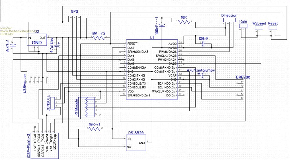
|
||||
palcal Guru Joined: 12/10/2011 Location: AustraliaPosts: 2039 |
I don't know about others but I gave up trying to convert a schematic into a PCB in DipTrace. I do away with the schematic and start with a blank PCB then I place the parts where I want them and route it by hand. Paul. "It is better to be ignorant and ask a stupid question than to be plain Stupid and not ask at all" |
||||
| panky Guru Joined: 02/10/2012 Location: AustraliaPosts: 1130 |
Hi Lew, As far as I can see it looks like you have the SPI clock (MOSI) connected to the BMP280 (temp and humidity?) but the SPI IN (MISO) connected to the Novalynx (wind speed, rain)? If the BMP280 is pin and functionally compatible with the DS18B20 then it should go to a standard digital in pin and keep the SPI pin for use as SPI. If the Novalynx uses SPI (as you have SPI MISO connected to it) then you also need the SPI Clk (MISO) connected to the Novalynx. But you're right about diptrace schematics - they are a b!@#$ to understand! 
Hope this helps, Doug. ... almost all of the Maximites, the MicromMites, the MM Extremes, the ArmMites, the PicoMite and loving it! |
||||
bigmik Guru Joined: 20/06/2011 Location: AustraliaPosts: 2981 |
Hi Lew, If you like, once you are happy with the accuracy of the circuit, give me a PM and we can discuss a PCB design.. I have a couple of ideas... But I would redo the schematic in Autotrax DEX as that us what I use.. I can follow the diagram above but I HATE the wires going through the components as in the diagram above so I would need a higher resolution copy of that diagram... Are you hoping to do this as a commercial product or is it a small project for yourself? If commercial, then I will ask some form of payment (modest to small) or if you wish to make the whole thing public including the code I will do the board and make the artwork available for all to use.. Now I also would prefer to use a MINI USB connector rather than micro for several reasons, including I have them and use them in my other projects.. But this is no deal breaker, in fact I suspect the foot print may even be the same or near enough to be interchangeable.. Possible ideas include, A new board complete for the job Or A plug in board for my MuP (you will find details in the link in my signature below) which already has console, ICSP, power supply and PiC support components so it only really needs to be an IO interface . I am away for a few days so it might take me a few more days to settle back before I could do them.. Regards, Mick Mick's uMite Stuff can be found >>> HERE (Kindly hosted by Dontronics) <<< |
||||
| matherp Guru Joined: 11/12/2012 Location: United KingdomPosts: 11604 |
If it is a one off use stripboard. You should be able to export the netlist to VeeCad and then the layout is easy and I find it quite relaxing |
||||
| HankR Senior Member Joined: 02/01/2015 Location: United StatesPosts: 209 |
Any way of doing such a board is fine, but I like the idea of having it be a plug-in. |
||||
| MicroBlocks Guru Joined: 12/05/2012 Location: ThailandPosts: 2209 |
I am pretty good with diptrace. If you send me the BOM i can make sure the parts have the correct footprint for making a pcb. Just as it is now most parts have footprints that not 100% correspond with what they are. So starting with that will make the process of creating a PCB much easier. Choosing 'convert to PCB' in the 'File' Menu, the doing a auto placement, dragging the connectors to the perimeter of the board and doing autoroute i get this: 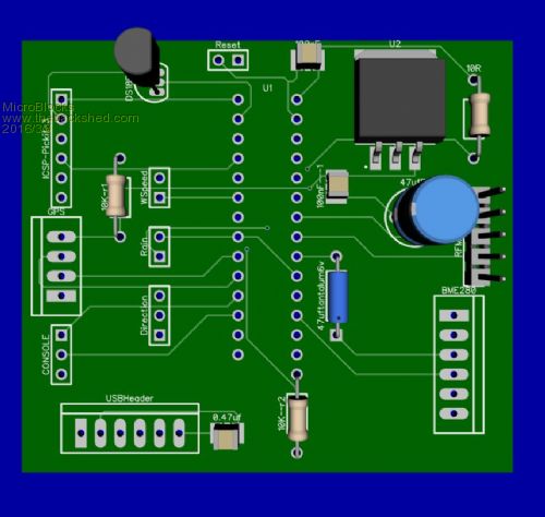
Once the correct footprints are done, and some manual routing this can be half the size and will look pretty decent. The one in the picture is 65x55mm. That was done in under a minute. :) edit: I cleanup your schematics, so that it has no lines going over components. I would however consider reviewing your schematic as currently it only supplies about 1A on the 3.3v line. It is also going to a RF module and a GPS module. Both of those can use much more power. And are you also sure everything is using 3.3v? I'll post the schematics here after i am happy with it. :) edit2: Ok done the schematics: 2016-03-08_063322_Weather2.pdf Diptrace schematic file: 2016-03-08_063650_Weather2.zip Please check the schematics, if everything is all right a PCB is easy to make. Microblocks. Build with logic. |
||||
| HankR Senior Member Joined: 02/01/2015 Location: United StatesPosts: 209 |
Actually I think 1A should be plenty because the HC-12 has a maximum draw of 100 mA and can be less if an output lower than +20 dBm is selected, and modern GPS ICs and antennas will draw well under 50 mA in continuous mode, even less in power saving mode. 17 mA and 5mA (power save) at 3.3 volts are easy to achieve for the GPS. |
||||
| MicroBlocks Guru Joined: 12/05/2012 Location: ThailandPosts: 2209 |
Here is a new PCB layout. It is 50x44mm so it can be made cheaply by many of the online PCB manufacturers. 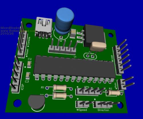
Diptrace PCB file: 2016-03-08_084500_Weather2_pcb.zip These files might help you get going. Once you know diptrace a bit, it can be used to make designs and pcb's pretty quickly. Microblocks. Build with logic. |
||||
| lew247 Guru Joined: 23/12/2015 Location: United KingdomPosts: 1709 |
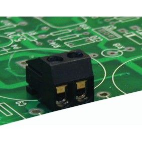
Wow I'm overwhelmed Thank you so much everyone for all your help, this is amazing I have no plans whatsoever for commercializing it as most of the code on the project came with lots of help from several members here. I'd never have done it without their help I say "done" it's still a work in progress, most of the code for the outdoor unit is working, I am using a MM+ to test each section one bit at a time, and once it's all working put it together properly. The plan is - outdoor unit consisting of: Wind direction (I'm using a NovaLynk 200-ws-23 simply because I got a great deal on Ebay for a 2nd hand one) Wind speed (Novalynx 200-ws-23 but the code will show how to adapt for any unit) Tipping bucket rain gauge GPS unit - any will work BME280 temp, humidity and pressure module - only using the humidity and pressure DS18B20 for temperature because it's more accurate than the BME280 HC-12 433Mhz rf tx/rx unit one mounted on the outdoor unit and an identical one on the indoor unit A mini USB connector supplying the power 3.3v regulator ICSP header Console header All the above will be mounted/connected to headers on the board so if any unit fails it can be replaced in seconds. Even the pic chip will be socketed so it can be replaced. The indoor unit at the moment I plan on using a MM+ with a 7 inch touchscreen but I am not even thinking about what it will show or how it will look until the outdoor unit is finished and working properly. I'll use the 2nd 433Mhz unit connected to the computer to display the information till I start working/finish the indoor unit bigmik I Didn't know about your MuP, if I had it would have made things a lot simpler working it all out It's a great idea making it as a plug in board for your unit, however if that was the case I wouldn't need the pic chip and several components. As I live in the UK it's not easy getting stuff from Australia so for the moment I think it's best to keep it as a seperate board (HOWEVER once its working properly I have no objections to you making a seperate board available for your MuP if you want - it would be easy enough for you to incorporate) MicroBlocks what can I say.. your a star. What you have done in a very short time is nothing short of incredible. Thank you so much. I'll send you a message after I've posted this. As to the BME280 Yes its powered from the SPI port on the Micromite - I used this port because it was free - but any port can be used, it doesn't have to be this one. The reason for powering it from the Micromite which a lot of people will hate is - On long time test over a week it kept failing at irregular intervals when powered from either 5v or 3.3v It would lose the connection for a period of time then start working again afterwards. The way I fixed it was powering it from the port (it only uses about 5mA) and only enabling the port just before taking the reading and powering down the BME280 after each reading. I tested this over a period of time and it works fine. Some may have a better idea which I'm open to ideas. MicroBlocks - I actually don't have a BOM simply because I couldn't find all the bits I needed on Diptrace so plan on making it with standard sized resistors/capacitors and so on I'll message you with what the bits are afterwards SMD components would make the board size a lot smaller, however my soldering skills with my eyes these days prohibit me from soldering smd components. Shame as it would be so much neater probably even using 1208 sized components. I'm not certain if using headers for the Wspeed, direction and rain connections is the best idea, or using those screw connectors like these 
Hopefully I haven't forgotten anything Lew |
||||
| MicroBlocks Guru Joined: 12/05/2012 Location: ThailandPosts: 2209 |
Yes those screw connectors look nice. It all depends on how you connect them, what cable you use etc. For diptrace it does not really matter much as in the schematic you can just change it to another connector and then 'update' the pcb. Screw terminals are a bit bigger, so maybe need to move them around a bit to make it fit. As for pcb's, it is best if you can keep it within a 5x5cm, or next step a 10x10cm. Those sizes are super cheap to order and betas having to make your own. Most offer 10 pieces for around 9-12 US$. Microblocks. Build with logic. |
||||
| bigmik Guru Joined: 20/06/2011 Location: AustraliaPosts: 2981 |
Hi Rob, Most people in the UK get their boards from me in 5 business days... But if you are in a rush WhiteWizard resells my boards and is UK based... Ini Any way It looks like Jean has you all sorted out.. So that is all a moot point. There are 2 'common' sizes of screw headers. 0.2" spacing and there are also 0.1" spacing, the 0.1" are actually quite good and fit in the same space as the standard pin headers... Regards, Mick Mick's uMite Stuff can be found >>> HERE (Kindly hosted by Dontronics) <<< |
||||
| MicroBlocks Guru Joined: 12/05/2012 Location: ThailandPosts: 2209 |
Well, to be honest i really think a mup will get things done quicker. If you add the time to wait for the pcb to be manufactured, then populate it and test it. A few weeks go by quickly. With a mup you can start within a few days and build from a known pcb that has been proven to work. Especially when it is a one-off that seems to be the most efficient way. A special PCB will look more professional, but if you are the only one who looks inside the box...    Microblocks. Build with logic. |
||||
| lew247 Guru Joined: 23/12/2015 Location: United KingdomPosts: 1709 |
I totally love your layout MicroBlocks, its amazing what you have done. I've settled on screw terminals for the battery connection, its easier than using a usb port. bigmik I've sent you a pm regarding your idea of making a plugin for the MUP, again it's a brilliant idea and so simple as well What I think would be the best idea, is get both ideas working and then once all the code is sorted properly, IF anyone else wants to make one they have the option of building their own "all in one" board Or Using a MUP with a plugin board. Hopefully that makes sense Lew |
||||
| MicroBlocks Guru Joined: 12/05/2012 Location: ThailandPosts: 2209 |
Do you have a link to the 0.1" ones. I can't find them... Microblocks. Build with logic. |
||||
| lew247 Guru Joined: 23/12/2015 Location: United KingdomPosts: 1709 |
I found some that are 1.3mm http://www.maplin.co.uk/p/3-way-16a-pcb-mounting-terminal-block-rising-clamp-5mm-rh77j |
||||
| WhiteWizzard Guru Joined: 05/04/2013 Location: United KingdomPosts: 2991 |
Hi Lewis, If you were to go for an SMD version of a PCB; I will be more than happy to assemble it for you with SMD parts. Take a look at the MuP PCB - I have a few left in stock (and they fit nicely into an envelope for 'cheap(ish)' postage! You know where I am if you need to contact me for other options
WW Forgot to mention: Those Maplin terminals are 'BIG' by the way |
||||
| lew247 Guru Joined: 23/12/2015 Location: United KingdomPosts: 1709 |
The console should be marked TTL or console |
||||
disco4now Guru Joined: 18/12/2014 Location: AustraliaPosts: 1130 |
RS components link They have 2,3 and 6 way at 0.1" Regards Gerry F4 H7FotSF4xGT |
||||
| bigmik Guru Joined: 20/06/2011 Location: AustraliaPosts: 2981 |
Hi Lew, All, Of course eBay has heaps listed.. A simple search comes up with these... eBay Search They are fine for sensor wires but if you need to connect any decent power supply with thicker wires then best go to 0.2" spacing. Regards, Mick. Ps. I am back from holidays now and I will reply in more detail tomorrow. Regards, Mick Mick's uMite Stuff can be found >>> HERE (Kindly hosted by Dontronics) <<< |
||||
| Page 1 of 7 |
|||||
| The Back Shed's forum code is written, and hosted, in Australia. | © JAQ Software 2026 |
