
|
|
Forum Index : Microcontroller and PC projects : CNC machining for lightweight projects
| Author | Message | ||||
| HankR Senior Member Joined: 02/01/2015 Location: United StatesPosts: 209 |
This is the beginning of a new, properly titled thread for this topic. It's clearly not off-topic because of the tasks that can be done so well with this type of equipment for making panels, enclosures, and even PCBs. |
||||
| HankR Senior Member Joined: 02/01/2015 Location: United StatesPosts: 209 |
Jim, what machine(s) do you have/use? |
||||
| MikeO Senior Member Joined: 11/09/2011 Location: AustraliaPosts: 275 |
Great idea for the new thread and nice looking clamp Jim. My current interest has been the PCBs as per previous posts, I was pretty happy with the last one I did and am confident to tackle a couple of other projects soon. I am using Diptrace , tried Autotrax but unlike Mick I wasn't that taken with it, but busy in the interface BUT its probably more I had just not spend enough time with it. For CNC I then follow export the gerbers into CopperCam which does a good job of making the NC files. As mentioned I have a Carving 6040 and use a program/hardware called CNCUSB from Planet software. Mike Codenquilts |
||||
| viscomjim Guru Joined: 08/01/2014 Location: United StatesPosts: 925 |
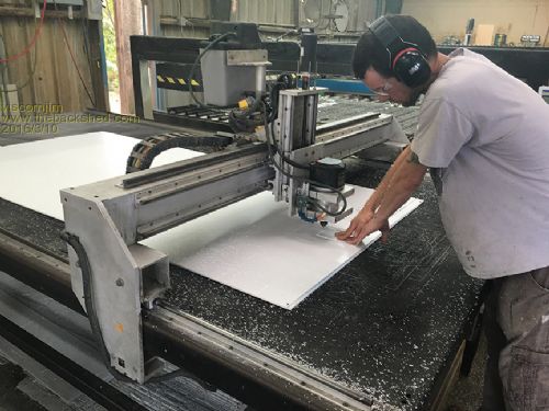
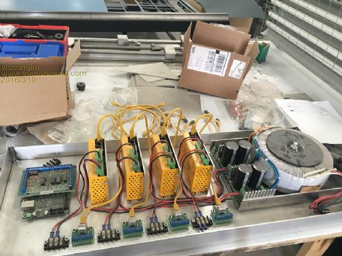
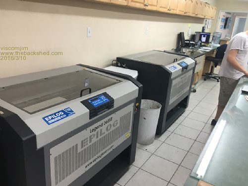
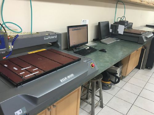
Hey Hank, I am in the sign business, so I have a few machines in the shop. The CNC routers I built myself, there are 5 of them and they are 5 foot x 10 foot beds. Also in the shop are 4 lasers and 2 16" x 24" engravers, large format digital printers, etc... Everything to make signs. My website is HERE to get an idea of what I make. I am lucky that I can use this equipment for my electronics hobby also. Fun, Fun, Fun... I am building another 5 foot x 10 foot router right now. Here are some pics... 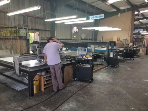
|
||||
| MikeO Senior Member Joined: 11/09/2011 Location: AustraliaPosts: 275 |
Jim.. I am going to stop posting on this thread Now, your going to know way more than I can contribute. Wow what a set up, nice to have seen the pics. Mike Codenquilts |
||||
| viscomjim Guru Joined: 08/01/2014 Location: United StatesPosts: 925 |
Hey Mike, I hope you keep posting because making pcbs with the mill is something I have never done and it would be great to do a 1 up instead of sending out and waiting for a couple of weeks to get the board back. I want to try the pcbs milling and I use autotrax dex to layout my boards. I will investigate how to actually do that with my software. Could you describe how you did the double sided board and made everything line up correctly? This is where the thought of it makes me nervous... |
||||
| paceman Guru Joined: 07/10/2011 Location: AustraliaPosts: 1329 |
Great setups you've both got I'd say, I'm quite jealous!  You're looking perplexed in that top photo Jim - did a bit just break or did the Bose's need adjusting? You're looking perplexed in that top photo Jim - did a bit just break or did the Bose's need adjusting? 
Greg |
||||
| viscomjim Guru Joined: 08/01/2014 Location: United StatesPosts: 925 |
Hi Greg, thats actually not me. I took the picture. Thats one of my awesome router operators, and, yes, I am wondering that myself... I hope it wasn't a bit, some of those cost $35 each. Ouch!!!! |
||||
| MikeO Senior Member Joined: 11/09/2011 Location: AustraliaPosts: 275 |
@ Jim, This is the process I use to make PCBs on my CNC. It has been a learning process of course and I am reasonably happy now with what I can produce, certainly good enough for my own projects or prototyping. I have settled on the following minimum sizes for tracks etc as it makes things easier during milling and construction. I use as a norm 0.8mm traces with 0.35 clearance in my rules. I use 1.8mm for via's . I try to make pad also 1.8 x 1.8 mm as a min. I use 0.6mm drills and 0.9mm for headers etc. I use Diptrace, I find very easy to use, I have tried Autotrax and I do have a licence but I think I have said before I find it a bit busy. 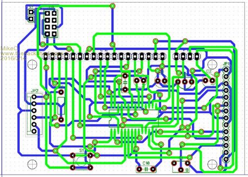
For CNC there a a couple of things to be aware of apart from comfortable trace and via/pad sizes, also you need to isolate from routing the side of the board that you can't get to when soldering headers and the like. I usually hide the pads in Diptrace which will force the router to make a via away from the pad. This particular board used a SOIC device for the MPU which I had no problems milling. I produce my Gerbers and read them into CopperCam to finish off, CopperCam allows me to easily do hatchings arround areas to get rid of copper and set up allignment holes, make cutouts and add tabs etc. It also gives you a pretty good visual of the finished PCB in case you have missed things. Lastly It allows you to nominate an origin for milling I visually use a via or pad hole. I them make the NC files for the mill. Use a 0.5 - 0.75mm cut with a 20 degree V bit (it has a .2mm nominal dia ) 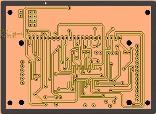
I use a a piece of HDF board on the mill, I used to mill an absolute flat and horizontal surface into the HDF to sit the PCB on but as my milling software has a Warping feature I now don't bother with the surface prep, the warp feature compensates for any irregularities due to clamping, in the copper board or the HDF. I Load the NC file, warp an area the size of the PCB, apply the warp Z adjustments. I set the Mill zero XY to the Origin/reference hole with the camera on the head and mill the top layer traces, drills and the alignment drills. The alignment drills go some 4-5 mm into the HDF board. I then turn the board over in the x direction, locate pins in the alignment holes into the HDF and clamp down the PCB. I load the NC file for the bottom traces (flipped in x), Locate the ref hole with the camera again and set the milling zero XY, warp the area of interest, apply the warp z adjustments. I then cut the bottom traces and follow with the drills. Lastly I do any cutouts and board outline, I usually have placed hold down tabs on the outline. And the finished PCB (sorry didn't have a photo prior to construction) 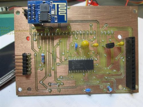
Mike Codenquilts |
||||
| The Back Shed's forum code is written, and hosted, in Australia. | © JAQ Software 2026 |
