
|
|
Forum Index : Microcontroller and PC projects : Micromite v5.1- console not working
| Author | Message | ||||
| rogersan Regular Member Joined: 10/04/2015 Location: AustraliaPosts: 79 |
I have programmed 3 X 28 pin Micromite v5.1 using the Arduino Nano (Silicon Chip Nov 2015). The hex file is micromite_5.1.hex from Geoff's website. Programming each microprocessor took about 4 minutes and there were no error messages. I cannot get a prompt back from any of these Micromites. The Console Tx is not going high as it should when it is idle. It does not seem to be programmed as an output. Is there a problem with V5.1? |
||||
| robert.rozee Guru Joined: 31/12/2012 Location: New ZealandPosts: 2541 |
are the chips you are programming MX170 devices, not MX150's? i've had no problems with the 5.1 firmware myself, but it only works on th MX170. naturally, i'm using an arduino nano based programmer, one of grogster's excellent kits: http://www.rictech.nz/pages/5/Products cheers, rob :-) |
||||
| rogersan Regular Member Joined: 10/04/2015 Location: AustraliaPosts: 79 |
I have found that you have to have the LCD Display connected for the Console Tx (pin 11) to be set as an output. The v5.1 must check for an LCD Display before setting up the serial console port. However I still cannot get any prompt back from the Micromite, the console Tx (pin 11) is still not sending any data. |
||||
| rogersan Regular Member Joined: 10/04/2015 Location: AustraliaPosts: 79 |
Is it possible that I have screwed up the LCD Display so that the Micromite cannot initialise it, so the Micromite is hanging and cannot reply via the Console Tx. I did enter the OPTION LCDPANEL a second time, perhaps this is enough to muck up the panel. |
||||
| robert.rozee Guru Joined: 31/12/2012 Location: New ZealandPosts: 2541 |
can you completely disconnect the LCD? |
||||
| rogersan Regular Member Joined: 10/04/2015 Location: AustraliaPosts: 79 |
If I disconnect the LCD Display the console still does not work, pin 11 does not get setup as an output so it cannot work. I think the setup does not proceed unless a display is detected. |
||||
| robert.rozee Guru Joined: 31/12/2012 Location: New ZealandPosts: 2541 |
now try reprogramming the MX170. if possible, capture the output from pic32prog and post it here. |
||||
| rogersan Regular Member Joined: 10/04/2015 Location: AustraliaPosts: 79 |
I do not know how to send the contents of a command window. I have photographed it on my IPad but it seems to be too large to attach. I could send the photo directly to you if I get your email address. |
||||
| robert.rozee Guru Joined: 31/12/2012 Location: New ZealandPosts: 2541 |
screenshot received. everything looks pretty much in order, and you are using exactly the same version of micromite basic as i am programming into MX170 chips here. next, can you check a few things: 1. that there is a 10k pullup resistor connected from pin 1 (MCLR) to pin 13 (3v3) on the processor. check the resistance at the IC socket using a multimeter if possible. 2. that there is a 10uF or thereabouts capacitor between pins 19 and 20. if the capacitor is polarized, make sure the + end is towards pin 20. 3. that all pins on the processor chip IC socket are soldered. 4. that the writing on top of the processor reads "MX170F256B". 5. that when power is applied, there is approximately 3.3 volts between pins 8 and 13 on the processor. pin 8 is -ve, pin 13 is +ve. cheers, rob :-) |
||||
| rogersan Regular Member Joined: 10/04/2015 Location: AustraliaPosts: 79 |
I double checked all connections. When I put a capacitance meter between pins 19 and 20, I found an intermittant connection to the 47 mF ceramic surface mount capacitor. I resoldered it and added extra solder and it is now working again. It did appear visually to be soldered properly before. Thanks for all your help. Roger Sanderson |
||||
| robert.rozee Guru Joined: 31/12/2012 Location: New ZealandPosts: 2541 |
that capacitor does seem to be the root of all evil - time and again a whole variety of problems keep getting traced back to it. i've never had problems with it myself, but so many other folks have. btw, would you mind posting a photo of your programmer (arduino nano setup) online? it is nice to see that folks are using this method of uploading firmware. cheers, rob :-) |
||||
| rogersan Regular Member Joined: 10/04/2015 Location: AustraliaPosts: 79 |
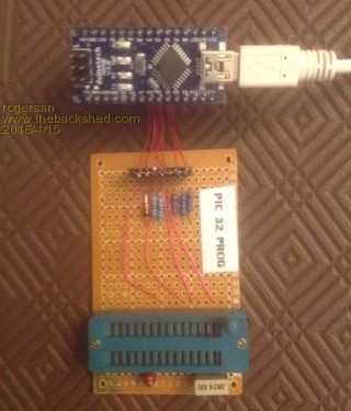
Here is a photo of my programmer using the Aduino Nano. |
||||
| The Back Shed's forum code is written, and hosted, in Australia. | © JAQ Software 2026 |
