
|
|
Forum Index : Microcontroller and PC projects : LCD Backpack 3.3 Volt Stability.
| Author | Message | ||||
| Phil23 Guru Joined: 27/03/2016 Location: AustraliaPosts: 1667 |
Been playing with some thermistors I calculated co-efficients for & getting lousy results compared to the DS18B20's. Reading high. Checked the power rails on the board & found the 3.3v rail to be pretty unstable. Moves between 3.3 & have noted it at 3.9v. 5 Volt supply from the plug pack feeding it seems rock solid. Only things on the 3.3 are the RTC & a single thermistor. Could it be anything other that a dodgy reg? Thanks Phil. |
||||
| MicroBlocks Guru Joined: 12/05/2012 Location: ThailandPosts: 2209 |
Change the caps first. When they are not good the regulator can not do its thing. Which regulator is used? How did you measure it? DVM (unreliable) or a scope. Microblocks. Build with logic. |
||||
bigmik Guru Joined: 20/06/2011 Location: AustraliaPosts: 2981 |
Gday PHIL, Which backpack? Is it one of mine (BackPack170 or SMD-BackPack170)? Regards, Muck Mick's uMite Stuff can be found >>> HERE (Kindly hosted by Dontronics) <<< |
||||
| Phil23 Guru Joined: 27/03/2016 Location: AustraliaPosts: 1667 |
Measured with a DVM (Fluke 77). Have seen it range from 3.37 up to 3.9, possibly time/temp dependent. During that period the 5.0V is always rock solid. (Both rails were the first thing I tested after assembly & were spot on & stayed the same on installing the micro). Purchased it from Silicon Chips Website, so not sure of the real origin. Just replaced the 47�F & both 10�F caps with tantalums & it's now sitting on 3.37V. It's blindingly obvious in hind sight what was going on; some DS18B20's sitting rock stable, & the Thermistor reading all over the shop, up to 5�C higher & generally drifting. Drift would start within a matter of minutes of start-up. Will have to say I was never impressed with the fact that Silicon Chip supplied 3 SMD caps instead of the Tantalums in Geoff's article. Firstly, having to deal with them with less that correct equipment, & tired eyes. Secondly, they weren't identified, just taped to a bit of paper, no markings, & I could only make a guess at which were which; 2 looked more similar than the 3rd & were maybe grouped a bit closer on the piece of paper. And then, only assume the correct values were supplied. Does make me wonder in hind sight how many of the other little hiccups if noticed have been related back to the 3.3 volt rail, (like ESP8266 stability). Rant over now. Cheers Phil. |
||||
| bigmik Guru Joined: 20/06/2011 Location: AustraliaPosts: 2981 |
Hi Phil, No not one of mine. (My `site', with the manuals for my boards is in my signature at the bottom of all of my messages). Glad you have it working, I would have, as MicroBlocks did already, pointed you to the caps.. Just a word of warning when it comes to SMD Tantalums.. The BAR indicates the POSITIVE side.. Regards, Mick Mick's uMite Stuff can be found >>> HERE (Kindly hosted by Dontronics) <<< |
||||
| Phil23 Guru Joined: 27/03/2016 Location: AustraliaPosts: 1667 |
They were not SMD Tantalums, they supplied non-polarised SMD ceramics. Cheers Phil. |
||||
| MicroBlocks Guru Joined: 12/05/2012 Location: ThailandPosts: 2209 |
I only use ceramics and never have any problems with them. I use MCP1700, TC1262 regulators. Maybe the used regulator has requirements that are not met with the supplied capacitors. They can be very critical, not enough capacity or too high ESR and it won't work reliable. Microblocks. Build with logic. |
||||
| robert.rozee Guru Joined: 31/12/2012 Location: New ZealandPosts: 2541 |
it would be interesting to find out what the measured values of the capacitors is. that they were not supplied on machine-feedable tape is a little odd. cheers, rob :-) |
||||
| Phil23 Guru Joined: 27/03/2016 Location: AustraliaPosts: 1667 |
Did actually measure them yesterday, found my old circa '80's DSE capacitance meter & also realised the cheap QM-1323 also measured caps. All devices measured in tolerance, but it did surprise me the amount of effort required to get a reading, Ie end pressure on the caps. Maybe heat damage from removal though. All that said the rail is still no good & climbs to around 3.7. On the scope (USB) I also see some noise when it polls the DS18B20's (5 ATM). Have yet to change to 2 0.1�F, can someone explain their purpose, out of interest. Have spare Regs too, both MCP1700 (TO-92) & AMS1117 (SOT-89). Given the reg on the backpack is very low current rated (200mA?), could it be my load that's causing the voltage to gradually climb? It which case, can I just add the other reg in circuit & have them "fight" each other or do I need the remove the First if I add the larger one. (My electronics is rather rusty these days, but having my daily does of WD-40). Thanks Phil. |
||||
| bigmik Guru Joined: 20/06/2011 Location: AustraliaPosts: 2981 |
GDay Phil, This is the schematic of the Power Supply circuit I use for my MuP and indeed the entire range of my 'mite range and it has been working very reliably (touches wood as I type that).. 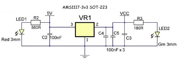
The 3 capacitors on the output stage are basically because they appear around the board there are only 2 100nf caps near the VReg, 1 on the input, 1 on the output.. The specs state there should also be a 47uf on the input but using good clean 5v supplies (such as USB and "plug-pack/wall-wart" chargers) I have not heard of any issues as you are seeing.. Kind Regards, Mick Mick's uMite Stuff can be found >>> HERE (Kindly hosted by Dontronics) <<< |
||||
| MicroBlocks Guru Joined: 12/05/2012 Location: ThailandPosts: 2209 |
If you use a MCP170x you need between 1uF and 22uF on the output side for a stable output. (According to the datasheet). Voltage should never climb, i would replace the regulator. However first check if it is not something else. Are you also using components that use 5v? Maybe they are 'leaking' to the 3.3v rail through some ic/resistor/capacitor etc. Microblocks. Build with logic. |
||||
| The Back Shed's forum code is written, and hosted, in Australia. | © JAQ Software 2026 |
