| Author |
Message |
Grogster

Admin Group

Joined: 31/12/2012
Location: New ZealandPosts: 9066 |
| Posted: 12:13am 06 May 2016 |
 Copy link to clipboard Copy link to clipboard |
 Print this post |
|
Hi folks. 
Having routed 64 digital inputs using the standard pull-up arrangement, I discover that I have actually made a slight mistake with the layout, and the 1k resistor on the input pin is actually on the 'Wrong' side of the 10k pull-up.
See this schematic:
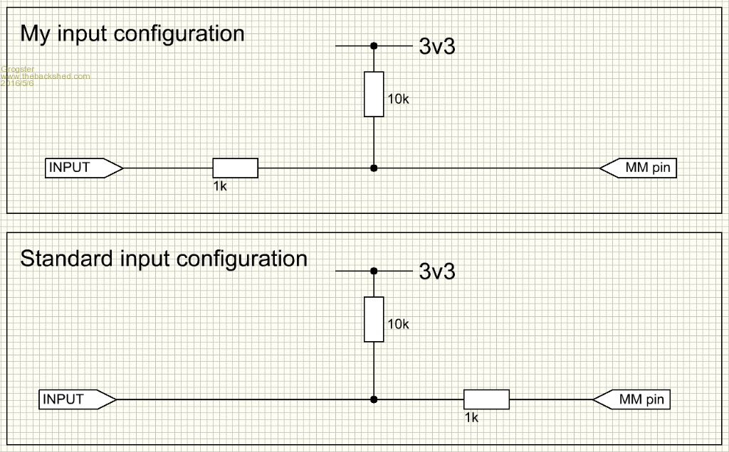
My question is simply: Do I need to change this, or will it still work?
The code detects if the pin is low, and as you can see, it is normally held high with the 10k pullup resistor.
My brain is saying that my configuration should still work, as the 10k will provide a pullup for the pin, and the 1k will limit any current when that input pin is grounded.
IE: My brain is saying that the location of the 1k should not really matter for standard high/low inputs, and that the 1-to-10 ratio should still mean that despite the 10k directly to to the I/O pin, the 1k will allow the pin to go low enough for the code to see that as a low level etc. But as there are 64 of these input arrangements, I figured before I make a 64-input mistake, I would just throw the idea out there in case my brain has it wrong.
...I need to know NOW if my configuration would not work, and I will put in the time and alter the layout. But I am hoping this will not be needed as rerouting 64 inputs will be a pain in the posterior.
EDIT: Come to think of it, I think I am safe. The PULLUP option on the SETPIN command just enables the weak 100k pullup, which I expect is direct to the pin anyway. One just wonders sometimes if one has it right, is all.  Edited by Grogster 2016-05-07 Edited by Grogster 2016-05-07
Smoke makes things work. When the smoke gets out, it stops! |
| |
matherp
Guru

Joined: 11/12/2012
Location: United KingdomPosts: 8592 |
| Posted: 12:47am 06 May 2016 |
Copy link to clipboard |
Print this post |
|
Grogster
I think you know the answer. Your circuit will work in most circumstances but you have created a voltage divider on the input which means that the effective input voltage needed to get a zero read has been lowered from the normal CMOS value.
The correct solution is to put the slog work in to correct the problem otherwise you will always know it is not as it should be. |
| |
Grogster
Admin Group
Joined: 31/12/2012
Location: New ZealandPosts: 9066 |
| Posted: 12:56am 06 May 2016 |
Copy link to clipboard |
Print this post |
|
Understood. I was hoping I could wing it, but part of me was not to happy about my "Mistake".
Curses. 
Let the editing begin........
Smoke makes things work. When the smoke gets out, it stops! |
| |
robert.rozee
Guru
Joined: 31/12/2012
Location: New ZealandPosts: 2290 |
| Posted: 02:33am 06 May 2016 |
Copy link to clipboard |
Print this post |
|
my answer would be that it doesn't really matter. the level that the pins see are shifted by less than 10%. if you are really worried, make the pullup 22k.
cheers,
rob :-) |
| |
Grogster
Admin Group
Joined: 31/12/2012
Location: New ZealandPosts: 9066 |
| Posted: 02:45am 06 May 2016 |
Copy link to clipboard |
Print this post |
|
You waited till I had almost finished changing the layout before you posted that, didn't you Rob. 
Oh well. I have changed more then half of it now, so I will just keep going.
I wish I had paid more attention to the layout in the beginning.
Rerouting tracks a 2nd time is.....annoying. 
Smoke makes things work. When the smoke gets out, it stops! |
| |
robert.rozee
Guru
Joined: 31/12/2012
Location: New ZealandPosts: 2290 |
| Posted: 03:43am 06 May 2016 |
Copy link to clipboard |
Print this post |
|
re-routing is good practice... did you take up the autotrax dex offer in the end?
i'd actually only skimmed your original posting, and assumed you'd already had the boards manufactured. since you've now redone the routing, you could probably use 10k for both of the resistors.
cheers,
rob :-) |
| |
Grogster
Admin Group
Joined: 31/12/2012
Location: New ZealandPosts: 9066 |
| Posted: 04:24am 06 May 2016 |
Copy link to clipboard |
Print this post |
|
Heh, heh!
No, did not take up Autotrax DEX offer.
It was a very good offer, but I am so used to using Sprint Layout 6, that I just decided to stay with it.
Have not made the boards, no. I noticed this issue before I sent it off, so that is a good thing.
I discovered that if I was careful and designed one side of things symmetrically, I could copy that side, flip it and paste it to the other side of things in one copy-and-paste operation, saving me lots and lots of separate tracks, so that will come in handy in the future.
I've almost finished making the changes.
Smoke makes things work. When the smoke gets out, it stops! |
| |
