Grogster

Admin Group

Joined: 31/12/2012
Location: New ZealandPosts: 9985 |
| Posted: 12:55am 15 May 2016 |
 Copy link to clipboard Copy link to clipboard |
 Print this post |
|
Hello folks. 
My latest 100x100 board contains a 100-pin MM+ and turns it into a glorified 64-I/O line controller unit. Originally, I was only going to design it as input-only specific for my purposes, but then thought it might be more useful to myself any others, if it were more configurable on-board, so that the one board could fit many situations where lots of I/O are needed.
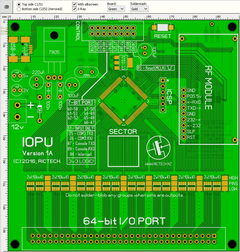
FEATURES:
- Up to 64 separate I/O lines, all on one box header
- All lines can be either inputs or outputs
- Simple solder-blob pads for input pull-ups or pull-downs
- Leave the solder-blobs off completely for outputs
- Configurable in blocks of 8 at a time per solder-blob
- Mix and match what you want, however you want.
- 1k load resistors on every one of the 64 I/O pins
- 7-bit output port with host interrupt line
- Standard serial-port output(COM3)
- Up to 16 control I/O's totally separate from the other 64
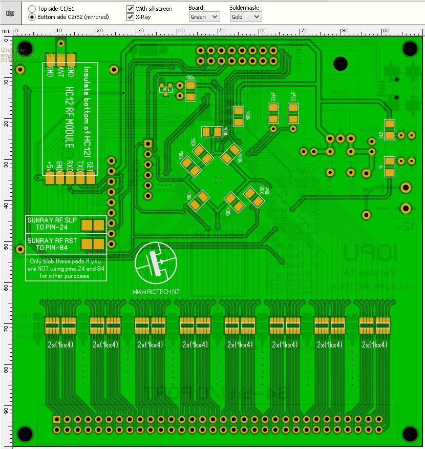
- Provision for SunrayRF 1022 type RF transceiver module
- Provision for HC12 type RF transceiver module
- USB interface + standard console
You can only use one type of RF module, and I was designing it mainly for the 1022 module, but I had the space, so it was easy to incorporate the HC-12 module, then you just install one or the other - the HC-12 is probably of most interest to forum members here, allowing you to build a wireless 64 I/O node if you wanted. You could setup many of these and have hundreds of wireless I/O lines if you wanted, all talking back to the host system.
The 7-bit port can be written as either input or output, and could, naturally, be less or more bits then I have on the silkscreen - this is just what I needed. It would be easy enough to change so that the port is an input, and it would SET one or more of the I/O pins on command from the host system.
I needed a serial port, so that is why COM3 is routed to the 16p box header, but there are no native I2C or SPI lines. This is no problem now that there are both I2C and SPI Cfunctions available, so you can configure your own I2C or SPI ports via the 16p box header pins if you prefer communication that way.
The 10k pull-up/pull-down resistor arrays are in 1206 size, and consist of four tiny resistors in each 1206 SMD package. Pin spacing is the same 0.5mm as the PIC32 chip. These 1206 resistor arrays are only about 2c each.
I will be releasing a very basic(no pun intended!) code for this once I have the PCB's back from the manufacturer, but I have no doubt others would be able to write craftier code then I for this board if so inclined. 
I will probably be making this board available from my website in blank board and kit form, if there is any interest past this post.
EDIT: There might be a small problem when used as outputs. Even with no solder-blobs, up to 8 pins will still be connected via the 10k arrays in a series circuit arrangement, so I will have to have a bit more of a think about that. IE: Any group of 8 pins, even with the blobs not there, will still have series 10k's to each other for each group of 8. A little hiccup there, as a result of my changing the design half way through. It seemed like a good idea at the time! 
EDIT: Here is the schematic for each group of eight pins:
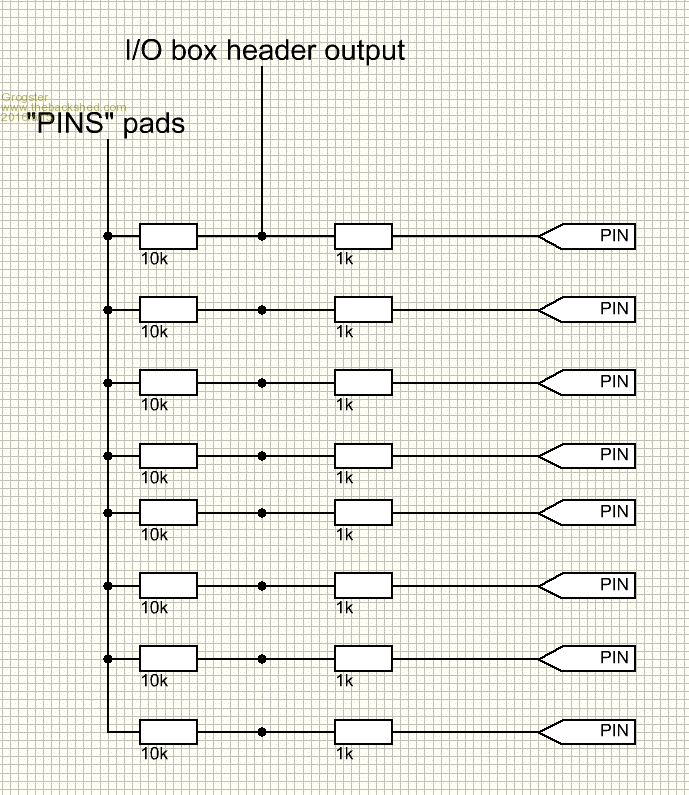
So with that in mind, to configure the pins as outputs, you would have to remove the small resistor arrays, or simply not install them if you knew how you were going to configure things. That is not that much of a problem to anyone who is happy working with SMD. As outputs, you would not want up to 8 pins being connected via the resistor pullup/down arrays I would think. Oh well. One small issue with the board, but as I say, if you know what you are wanting to do, either don't install them for outputs, or remove them.Edited by Grogster 2016-05-16
Smoke makes things work. When the smoke gets out, it stops! |
