
|
|
Forum Index : Microcontroller and PC projects : 1-Wire Cabling DS18B20’s
| Author | Message | ||||
| Phil23 Guru Joined: 27/03/2016 Location: AustraliaPosts: 1664 |
I've said a lot about multiple DS18B20's on a single bus. Here's how I intend to physically cable them. RJ-11 6P4C jointers easily pull in half, you can then cut the wires in half & join them to 2 devices. Using more joiners & M-FF double adaptors it is simple to install a bus with droppers. 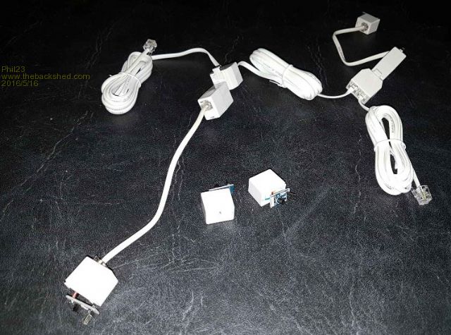

My total bus length will be about 30m, with about 8 droppers each about 2m. This seems well under some of the examples that are mentioned in these guidlines. How reliable it performs long term as far as connection reliability, I'll have to see. I do know my weather station contains 4 RJ-11 connections & has been exposed to the environment for over 5 years with no issues. Question I do have is; the modules each have their own 10k terminator. 8 on a bus is going to be well below the 4.7k recommended in the MM manual. Am I best to remove the resistors from each module? Also each module has a power LED; best to dispense with that as well? Thanks Phil |
||||
| akashh Senior Member Joined: 19/01/2014 Location: IndiaPosts: 115 |
A client of mine used about 15 of these, not sure if they were in a star arrangement or daisy chained, but he used a single pull up resistor at the mcu side, it was between 2.7 and 5.1k, you may need to play a bit to get it right, but there were no terminating resistors anywhere else. The exact sensors he used were the Chinese waterproof ones, with no LED or pull up. I would remove those if possible. Akash |
||||
| Phil23 Guru Joined: 27/03/2016 Location: AustraliaPosts: 1664 |
That was my thoughts, remove the 10k's. 8 of them would be giving me a pull up value of 1.2k at the processor. Pretty low. What about the LEDS? Any likely significance from the current they draw on the power line? Also using the waterproof ones where applicable. Thanks Phil. |
||||
| MicroBlocks Guru Joined: 12/05/2012 Location: ThailandPosts: 2209 |
A single LED will probably use between 10-20ma. Depending on your power source this could be huge or small. :) Microblocks. Build with logic. |
||||
| Phil23 Guru Joined: 27/03/2016 Location: AustraliaPosts: 1664 |
Ok, So initially my multi sensor 1-Wire bus didn't work. 4 sensors, 10m shielded cable down into the house, about 30m in total of non-twisted modular phone cable in star/bus configuration in the roof. Dropping back to a single sensor on 1m of modular cable & it worked, increased it to 5m and it wouldn't. Seemed to disagree with other examples I read about. Considered whether I needed to change the value of the pull-up resistor to change the load on the bus. That's when I discovered, Yellow-Violet-Black-Black-Brown.......... Another midnight haunting, (I'll blame the cats, they like to play with my breadboards). Seems I'd foolishly used 470 Ohms instead of 4.7k for the pull-up resistor, must have just been getting by with the previously connected single sensor. Changed the pull-up to the correct value & it's all running like a dream. Cheers Phil. |
||||
| paceman Guru Joined: 07/10/2011 Location: AustraliaPosts: 1329 |
Good find Phil - and well done. Time to get a dog maybe? 
Greg Edit: I never place a resistor till I've measured it first - maybe overkill - but just saying  |
||||
| Phil23 Guru Joined: 27/03/2016 Location: AustraliaPosts: 1664 |
Yeah brain fades near midnight, 4 7 0 0 not 4 7 0 x10^0. 3 Cats is enough, one likes wires (String! My favourite thing!), another seems particularly fascinated by modules hanging off jump leads with blinking LEDs. Cheers. |
||||
| Phil23 Guru Joined: 27/03/2016 Location: AustraliaPosts: 1664 |
Was a good day today to be not worried about the fan not running & climbing about in the roof space. Not a lot of warmth anywhere... [Code] Lounge Temp = 25.8 Bedroom Temp = 23.9 Ambient Temp = 8.3 Roof Temp = 8.9 Maximum & Minimum Temps Lounge Max = 27.5 Lounge Min = 24.0 Ambient Max = 13.1 Ambient Min = 7.8 Roof Max = 16.5 Roof Min = 9.5 System Status:- Current Up Time is:- 05:55:17 [/code] Cheers |
||||
| WhiteWizzard Guru Joined: 05/04/2013 Location: United KingdomPosts: 2794 |
@Phil23 Possible bug in your software going on the figures posted above. Roof Temp = 8.9, but Roof Min = 9.5 Not trying to find fault - just simply making you aware 
WW For everything Micromite visit micromite.org Direct Email: whitewizzard@micromite.o |
||||
| Phil23 Guru Joined: 27/03/2016 Location: AustraliaPosts: 1664 |
Thanks for pointing it out. Copy paste error. Actually grabbed the data from 2 captures to get correct maximums due to a restart. [Code] Lounge Temp = 25.8 Bedroom Temp = 23.9 Ambient Temp = 8.3 Roof Temp = 8.9 Maximum & Minimum Temps Lounge Max = 27.5 Lounge Min = 24.0 Ambient Max = 13.1 Ambient Min = 7.8 Roof Max = 16.5 Roof Min = 8.5 System Status:- Current Up Time is:- 05:55:17 [/code] Looks like we are in for 0�C tonight, already down to 6�. Cheers. |
||||
| Phil23 Guru Joined: 27/03/2016 Location: AustraliaPosts: 1664 |
The thought of adding a couple of DHT22's to the bus crossed my mind..... Not clear on what the data sheets are saying. Do they have individual serial numbers like the DS18B20's? So far I've only found basic data sheets, with no where near the depth of the DS18B20 data sheets. It's either do-able, or totally not. For anyone interested in using multiple sensors on a single wire here's what's Ive used. Firstly collected their serial numbers one at a time with this code:- [Code] '1-Wire Serial Number Search - One Device ONLY Attached. 'Code by Jman 02 April 2016 Option Explicit Dim OW1,OW2,OW3,OW4,OW5,OW6,OW7,OW8 Dim PinNbr PinNbr = 15 OneWire Reset Pinnbr OneWire Write PinNbr, 1, 1, &H33 ' Issue Read ROM command OneWire Read PinNbr, 2, 8, OW1,OW2,OW3,OW4,OW5,OW6,OW7,OW8 Print "Temp Sensor Should be 28 / ";Hex$(OW1);"H" Print "Serial# ",Hex$(OW2,2);Hex$(OW3,2);Hex$(OW4,2);Hex$(OW5,2);Hex$(OW6,2);Hex$(OW7,2);"H" Print "CRC ";Hex$(OW8,2);"H" 'Added this line so I can copy & paste the Serial numbers into a list text file '& from there to the code as needed Print "String for Code is:- &H";Hex$(OW2,2);Hex$(OW3,2);Hex$(OW4,2);Hex$(OW5,2);Hex$(OW6,2);Hex$(OW7,2);Hex$(OW8,2) [/code] Then read them with a function in my main code:- [Code] 'List of DS18B20's on the Bus. Dim Integer TsAmb1=&HFFE244001601E7 'Sensor1 Ambient Temp Dim Integer TsRoof=&HFF94580016013C 'Sensor2 Roof Temp Dim Integer TsLng1=&HFFA257001601BE 'Sensor3 Lounge/Dining Room Temp Dim Integer TsBed1=&HFF2C5A0016014A 'Sensor3 Bed Room Temp Dim Integer Ts1,Ts2,Ts3,Ts4,Ts5,Ts6,Ts7 Dim Float LTemp, HTemp, Status .. .. .. TempAmb1=ReadTemp(TsAmb1) TempRoof=ReadTemp(TsRoof) .. .. .. '========================OneWire Temperature Function========================= ' Get the temperatures from DS18B20 - multiple probes on a single pin '============================================================================= Function ReadTemp(TsSerial As Integer) As Float Ts1=(TsSerial >> 48) and &hFF : Ts2=(TsSerial >> 40) and &hFF : Ts3=(TsSerial >> 32) and &hFF Ts4=(TsSerial >> 24) and &hFF : Ts5=(TsSerial >> 16) and &hFF : Ts6=(TsSerial >> 8) and &hFF : Ts7=(TsSerial) and &hFF OneWire Write TsBus, 1, 10, &H55,&H28,Ts1,Ts2,Ts3,Ts4,Ts5,Ts6,Ts7,&H44 'Check sensor is ready Timer=0 : Status=0 Do If Timer > 1000 Then Error "Sensor Error" OneWire Read TsBus, 4, 1, Status ' Conversion status Loop Until Status = 1 OneWire Write TsBus, 1, 10, &H55,&H28,Ts1,Ts2,Ts3,Ts4,Ts5,Ts6,Ts7,&HBE OneWire Read TsBus, 2, 2, LTemp, HTemp 'Calculate the Temp in C ReadTemp=((HTemp And &b111) * 256 + LTemp) / 16 If HTemp And &b1000 Then ReadTemp=-ReadTemp ' adjust if negative End Function '===========================End of Temp Routines============================== [/code] TsBus (the pin number used) should probably be passed to the function, and I presume all of HTemp, LTemp & Status could be integers. Cheers Phil. PS. Credit for the final solution goes to all those who helped out. |
||||
| Phil23 Guru Joined: 27/03/2016 Location: AustraliaPosts: 1664 |
Think I've answer the DHT22 Question. [Quote] MaxDetect 1-wire bus is used for communication between MCU and RHT03. ( MaxDetect 1-wire bus is specially designed by MaxDetect Technology Co., Ltd. , it's different from Maxim/Dallas 1-wire bus, so it's incompatible with Dallas 1-wire bus.) [/quote] Seems the DHT22 is similar. Phil |
||||
| Phil23 Guru Joined: 27/03/2016 Location: AustraliaPosts: 1664 |
Usually follow a similar practice, but not on those lounge chair occasions around midnight. Cheers. |
||||
TassyJim Guru Joined: 07/08/2011 Location: AustraliaPosts: 5923 |
To start the DHT22, the processor pulls the data line low for 1ms. There is no way to address individually modules on the same data bus. Jim VK7JH MMedit MMBasic Help |
||||
