
|
|
Forum Index : Microcontroller and PC projects : Interfacing Relays
| Page 1 of 2 |
|||||
| Author | Message | ||||
| Phil23 Guru Joined: 27/03/2016 Location: AustraliaPosts: 1667 |
Firstly Excuse my rusty old head, but I'm confused by the contradiction here. Page 11 in the manual makes perfect sense, SETPIN(15),DOUT
PIN(15)=1 'On comes a LED PIN(15)=0 'Off goes the LED But when I come to interfacing commonly found relay boards, which all seem to a an active low input, the logic is reversed. SETPIN(15),DOUT,OC
PIN(15)=0 'Relay pulls in PIN(15)=1 'Relay drops out Is this reversible in configuration? Can see my head in a mess if logic 1 mean on in one place, while it's off in another place. Or is there a common way of easily inverting this in the hardware connections without going overboard. Thanks Phil |
||||
OA47 Guru Joined: 11/04/2012 Location: AustraliaPosts: 1050 |
Depending on the number of relays you are using you could use the ULN2003 IC (Jaycar ZK8855) will do up to 7 relays and offer protection for your pic. GM |
||||
| Phil23 Guru Joined: 27/03/2016 Location: AustraliaPosts: 1667 |
I know I can do it like this, but seems a bit cludgy. SETPIN(15),DOUT,OC
PIN(15)=NOT(1) 'Relay pulls in PIN(15)=NOT(0) 'Relay drops out Etc... |
||||
TassyJim Guru Joined: 07/08/2011 Location: AustraliaPosts: 6543 |
DIM Ron = 0, Roff = 1 . . . PIN(15)= Ron ' etc I usually us a ULN2003 or similar. VK7JH MMedit |
||||
CircuitGizmos Guru Joined: 08/09/2011 Location: United StatesPosts: 1427 |
' Constants CONST Relay = 15 CONST RelayOn = 0 CONST RelayOff = 1 CONST LED = 16 CONST LEDOn = 1 CONST LEDOff = 0 ' Port direction SETPIN(Relay),DOUT SETPIN(LED),DOUT ' Clicky/Blinky PIN(LED)=LEDOn1 'On comes a LED PIN(LED)=LEDOff 'Off goes the LED PIN(Relay)=RelayOn 'Relay pulls in PIN(Relay)=RelayOff 'Relay drops out Micromites and Maximites! - Beginning Maximite |
||||
| Benzol Regular Member Joined: 07/01/2015 Location: AustraliaPosts: 64 |
I am driving 5v relays direct from the micromite. From the above comments it looks like I'm doing it all wrong. Time to buy a ULN2003 and re-build! |
||||
Grogster Admin Group Joined: 31/12/2012 Location: New ZealandPosts: 9985 |
Benzol - naughty boy!  The back-EMF from the relay coil when the relay is switched off is the killer, but I expect that you have a back-EMF diode across the relay coil. However, that won't help you if you try to suck too much current out of the I/O pin...... The back-EMF from the relay coil when the relay is switched off is the killer, but I expect that you have a back-EMF diode across the relay coil. However, that won't help you if you try to suck too much current out of the I/O pin......
I also agree with everyone else - the ULN2003 is made for the purpose, and very cheap. That is how I drive all my relays if I have more then one or two on any one board. If I only have one or two relays, then a simple transistor buffer works extremely well. Smoke makes things work. When the smoke gets out, it stops! |
||||
| Benzol Regular Member Joined: 07/01/2015 Location: AustraliaPosts: 64 |
Yeah, kind of explains the switching transients giving me some bizarre happenings with the micromite and LCD screen. I had removed most of the problems with extra green caps but as the relay board (4 relays) had opto couplers I didn't think anything further of it. The day is wasted if I haven't learnt something new! This forum is so good. |
||||
| Grogster Admin Group Joined: 31/12/2012 Location: New ZealandPosts: 9985 |
If your relay board used opto-coupler drivers, then connecting the opto's directly to the MM pins is just fine. I assumed you had the relay coil directly across the MM I/O pin and ground, with perhaps a back-EMF diode across the coil. If you are using a board that uses opto-coupled inputs, then directly connecting THAT to the MM pins should not be a problem - in fact, it is one of the ideal ways to do it. Smoke makes things work. When the smoke gets out, it stops! |
||||
| Benzol Regular Member Joined: 07/01/2015 Location: AustraliaPosts: 64 |
Thanks Grogster The relay board specifically uses optos (http://aud.dx.com/product/4-channel-5v-optocoupler-isolation-replay-module-w-high-level-trigger-blue-961223433#.VzrBheR 9Zeo) but I still get some weird happenings. I sorted most out with an additional greencap on the 5v to the relays I will rebuild with the ULN and see what happens. I appreciate your help (again). |
||||
| erbp Senior Member Joined: 03/05/2016 Location: AustraliaPosts: 195 |
I recently purchased a 4 x 5V Relay module on Ebay. It has opto-couplers on each input so is safe to drive directly from a MM I/O pin. The one I got has a header with jumper for each channel allowing selection of whether a high or low level input switches the relay on. I don't know if all such boards feature this capability - from Ebay images I would say not, but it is hard to tell. Also it doesn't appear to be something the Ebay sellers include in their product descriptions, which is a bit unfortunate. |
||||
| TassyJim Guru Joined: 07/08/2011 Location: AustraliaPosts: 6543 |
That board looks similar to one I have. It should be easy to reverse engineer it and get the circuit. It should then be easy to change the sense so you can have active high or active low. I haven't done it with that board but I was successful with others. Jim VK7JH MMedit |
||||
| robert.rozee Guru Joined: 31/12/2012 Location: New ZealandPosts: 2541 |
hi, a couple of observations. (a) have you considered using the following code to redefine the values of 0 and 1 and hence reverse the relay operation: LET 0=1
LET 1=0 
(b) in my experience, radiated emissions are as problematic as conducted, with misbehaviour just as likely to be caused by sparking across a set of relay contacts as they open. https://en.wikipedia.org/wiki/Spark-gap_transmitter while a tonne of filtering at your microprocessor may go some way to partially mitigating the adverse effects of relay contacts switching a load, eliminating the problem at the relay contacts is a far simpler solution. this may be as simple as a small (suitably rated) capacitor across the relay contacts, replacing the relay with a switching transistor (or solid-state relay), or fitting the switched appliance/load with a common-mode filter. cheers, rob :-) |
||||
mikeb Senior Member Joined: 10/04/2016 Location: AustraliaPosts: 180 |
Hi all, If you use an NPN transistor from relay to ground then pin(n) = 1 works a treat. Don't forget the 'flyback' diode in parallel with the relay coil to protect the transistor from 'back EMF' spikes. Unless you use a transistor with a really crappy 'Hfe' then a base resistor of 4k7 will suffice. Use a BC547, or similar, and you'll be OK. Adjust your base resistor to make sure you have approx 0.6 to 0.7V across the transistor when it is on. That way you will know that it is fully saturated. There are 10 kinds of people in the world. Those that understand binary and those that don't. |
||||
| 5bar Newbie Joined: 10/07/2014 Location: AustraliaPosts: 16 |
I'll chuck in my two bob I've always used ULN2803 darlington drivers 3.3 or 5v, they're happy up to 50v My present setup with cgmm, is using uln2803 to switch 5v reed relays In a 14dip package Built in clamping diode, even Jaycar stock 'em I can count to 31 on one hand |
||||
| mikeb Senior Member Joined: 10/04/2016 Location: AustraliaPosts: 180 |
2803's are great for multiple relays. Use them all the time. Inbuilt flyback diodes and all. It sounded like the original post was for one relay only. Another option is using digital transistors (inbuilt base resistors). In the end there are heaps of ways to drive a relay. Depends on how many. ALWAYS REMEMBER THE FLYBACK DIODE TO ELIMINATE BACK EMF SPIKES. There are 10 kinds of people in the world. Those that understand binary and those that don't. |
||||
| Phil23 Guru Joined: 27/03/2016 Location: AustraliaPosts: 1667 |
Hi All, I now have a 4 Channel relay sitting in the roof space. This one to be precise. Some of mine even came with additional bent pins as a bonus... 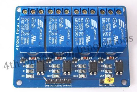
Connected is:- A 2 speed inline fan, 840�m/hour, draws 105 watts on high. A 240V motorised damper valve. Drive open/drive closed type. Relay connections are:- Channel 1 - Fan High Speed Channel 2 - Fan Low Speed Channel 1 - Damper1, NO contact to "Drive Open", NC contact to "Drive Close". Channel 1 - Spare Few Questions on Best Practices. It's connected via about 10 metres of Olex 8 Core data cable. (Had a roll in the shed from years ago. Might be something like AWG 26-28, not marked). Cable has foil shield & drain; Should I use it? Connect it at one end as per past practices with the likes of RS-232? Relay inputs are connected directly to the micro; should I add a cap to each? Relay coils are currently powered by the same 5v supply on the micro end. Relay coils seem to draw about 70mA each, so putting about a 150mA load on the 5V supply & same current in the cable. (1 fan relay & damper relay held in for most of the day). Alternatively the relay board could have it's own 5V supply in the ceiling space. (Yes I have power points up there.... and lights.... and hardwired smoke detectors.... and a 300mm wide walkway). What are the opinions on Best Practices to avoid issues that may crash the micro? Thanks Phil. |
||||
| OA47 Guru Joined: 11/04/2012 Location: AustraliaPosts: 1050 |
Phil, I would definitely use the foil/shield in the cable connected to ground at the MM end. If you have the spare wires you could use the twisted pair for each relay to minimize interference. GM |
||||
| robert.rozee Guru Joined: 31/12/2012 Location: New ZealandPosts: 2541 |
i'd be inclined to power the relay board from a separate 7805 regulator. in fact, an unregulated 6v plugpack would almost certainly be fine - the relay coils will be more than happy with 6v or so. OA47's idea of using the spare wire in each pair as an extra ground is also a good one. or you could use 2 as power grounds, and 2 as Vcc supply. a 'ground wire' that is at Vcc potential will work just as well as one at ground. in this way, you can keep your 6v plugpack down at the micromite end. cheers, rob :-) |
||||
| mikeb Senior Member Joined: 10/04/2016 Location: AustraliaPosts: 180 |
Hi Phil23, I don't know why the chinese bother with 5V relays as they are such 'current hungry' beasts. You have a couple of choices. The shield isn't necessary, for noise suppression, as the inputs are very low impedance. They connect the Gnd to the optocouplers. No need for any caps either. The optocouplers merely serve as level translators, as the ground pins on both the 3 pin and 6 pin connectors are physically connected by the PCB copper ground plane, so they cannot serve as high voltage isolation. The yellow jumper connects the JDVcc +5V supply pin to the Vcc +5V supply pin of the 6 way connector. This allows you to run a seperate 5V supply for the relays if you leave it out. Proper operation with a 3V3 input voltage would surprise me as the combined series voltage drop across the indicator LED, internal opto LED and the series current limiting resistor (R1) would probably be a bit much. You would most likely be better off connecting Vcc, of the 6 pin connector, to +5V and configuring the uMite pin as open collector (make sure it is a 5V tolerant pin). Maybe it works at 3V3 (haven't tried it). It's just that the theory doesn't add up. Anyway, to get over voltage drop (10m of 26AWG @ 150mA) I would suggest the following - 1) Use the shield drain wire for Gnd pin of 3 pin connector. 2) One parallel pair of conductors for JDVcc pin of 3 pin connector. Leave out the yellow jumper. 3) No connection to Vcc pin of 3 pin connector. 4) Connect the above to a 5V (6V) supply of your choice. Observing polarity. Connect a plugpak (wall wart), as described above if you wish, and retain the spare conductors. Voltage drop will no longer be a problem. When you start off at 5 volts every bit counts. 5) One conductor for pin 6 of 6 pin connector. Connect to 3V3 (5V) on uMite board. 6) One conductor for each input and connect to respective uMite output pin. If pin 6 was connected to 5V ensure that any uMite pin is 5V tolerant and configured as open collector. See the drawing below for an idea of the circuit on your board. Only one channel shown. It is the best educated guess I could come up with just looking at pictures on the web. 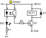
Hope this helps There are 10 kinds of people in the world. Those that understand binary and those that don't. |
||||
| Page 1 of 2 |
|||||
| The Back Shed's forum code is written, and hosted, in Australia. | © JAQ Software 2026 |
