
|
|
Forum Index : Microcontroller and PC projects : PSU help needed
| Author | Message | ||||
lew247 Guru Joined: 23/12/2015 Location: United KingdomPosts: 1709 |
Anyone any good with Power supply design? The 3.3V circuit is attached below, but it's giving problems. Unless an EXTREMELY clean 5V supply is connected it is corrupting the Micromite when the power is disconnected. So badly that it has to be reflashed with Micromite Basic and the complete program typed in again. Any ideas/thoughts/suggestions on why this is, or how to fix it? I suspect I might have "too much capacitance" and it's holding a charge when the power is disconnected and draining slowly corrupting the micromite. By "slowly" I mean slow in computer terms... miliseconds rather than microseconds. I want to keep the 3.3V regulator the same pinout but I don't mind changing the external circuitry. OR is it simply a case that the 5V input has to be Extremely clean? 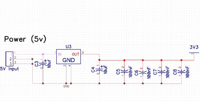
|
||||
redrok Senior Member Joined: 15/09/2014 Location: United StatesPosts: 209 |
Hi lew247; Not enough information. Show us the 5V circuitry. No, to much capacitance is not the problem. Generally the more the better. I suspect the 5V is not staying higher than 3.0V plus the regulators dropout voltage. What regulator are you using? redrok |
||||
| lew247 Guru Joined: 23/12/2015 Location: United KingdomPosts: 1709 |
Sorry forgot to put the regulator name in I'm using two MIC2940A-3.3BU or LM3940IS3.3 The 5V psu is a show bought 5v 1A psu - nothing special or fancy It's only corrupting the Micromite when the 5V psu is removed |
||||
| redrok Senior Member Joined: 15/09/2014 Location: United StatesPosts: 209 |
Hi lew247; What is the minimum current drawn from the MIC2940A. The minimum in the spec is 5ma. See the spec: If you are using the LM3940IS3.3 you don't have enough output capacitance. See the spec:Both of these regulators are high performance types and the specifications for capacitance is critical. redrok |
||||
| redrok Senior Member Joined: 15/09/2014 Location: United StatesPosts: 209 |
Hi lew247;How are you "Removing" the 5V PSU? Are you unplugging a "Wall Wort" type from the power line? This can cause havoc due to sparking. Simply switching the 5V off would not cause problems. redrok |
||||
| lew247 Guru Joined: 23/12/2015 Location: United KingdomPosts: 1709 |
The MIC2940A-3.3BU I wonder if I added 2 X 1K resistors in parallel on the putput to the chip which "should" give 6.6mA load if my calculations are correct) would help it. The LM3940IS3.3 I forgot to mention has a 47uF capacitor on the output, not the 10uF, I wonder if that would help the MIC2940A-3.3BU as well? |
||||
| redrok Senior Member Joined: 15/09/2014 Location: United StatesPosts: 209 |
Hi lew247;You don't need the 5mA load on the MIC2940A-3.3BU. But you do need it on the LM3940IS3.3. Two 1K resistors will work fine.The 47uF is acceptable. However, I don't think this is causing your problem. It sounds like the problem is in how the 5V PSU is being turned off. Use a switch between the 5V PSU and your 3.3V regulator. redrok |
||||
disco4now Guru Joined: 18/12/2014 Location: AustraliaPosts: 1130 |
Are you using atleast MMbasic 5.0. There was an issue way back when disconnecting power. (4.7 I think) Gerry F4 H7FotSF4xGT |
||||
| lew247 Guru Joined: 23/12/2015 Location: United KingdomPosts: 1709 |
Thanks - on/off switch simplest things are always forgotten. |
||||
| WhiteWizzard Guru Joined: 05/04/2013 Location: United KingdomPosts: 2991 |
I am helping build this system so can answer some points here: @disco4now MMBasic v5.1+ @redrok MIC29300 3v3 is being used with 10uF caps. The 5V PSU when removed from the mains socket does not cause issue. And when the USB lead is disconnected at the PSU end there is no problem (NOTE: USB lead from PSU goes to 'external 5v input on PCB via header pins). BUT - I had a 'loose/worn' jumper pin from the USB PSU to PCB causing the +5v power line to 'bounce' - it was this resulting consistently in wiped firmware. Whenever I went to pack away the setup, I would move this loose lead, resulting in a wiped chip. BUT whenever I switched off the 5v external PSU first (before moving the loose connection) everything worked as it should. For those involved in the early days of Beta testing - this was a real headache for Geoff - but a design was worked on that prevented this 'wiping'. The only thing I can think off is that Pin 34 (USB detect) is still getting power, and with a 'bounced' 3v3 PIC power, perhaps the 'internals' of the PIC are causing the 'wipe'. As mentioned here - a switch will resolve the issue - I am just surprised that with caps on the 3v3 line that this situation arises. I have emailed Geoff and will await his valuable input . . . . WW |
||||
bigmik Guru Joined: 20/06/2011 Location: AustraliaPosts: 2981 |
GDay Lew, WhiteWizard, My suggestions are (in order) as follows: 1. USE a CLEAN 5V source There a a million different iPad chargers out there that will suffice. 2. Put a larger filer cap (around 1000uf) across the input and a 47uf across the output. 3. Knowing Phil he has probably used his 10uf VCap, Not wanting an international `fisty cuffs' but try a low ESR 47uf tantalum instead. Kind Regards, Mick Mick's uMite Stuff can be found >>> HERE (Kindly hosted by Dontronics) <<< |
||||
| The Back Shed's forum code is written, and hosted, in Australia. | © JAQ Software 2026 |
