
|
|
Forum Index : Microcontroller and PC projects : SPI data pin...
| Author | Message | ||||
| Zonker Guru Joined: 18/08/2012 Location: United StatesPosts: 772 |
Concerning the standard SPI data port, is there a way to provide a "soft" pull-up on the data pin.? I know I could just use a 10k resistor, but was wondering if there is a "no part" way to do the same thing and tell the MM to turn on the internal pull-up resistor for the SPI data pin... The reason I ask is after testing some prototype code using a couple of MAX31855 IC's, I wanted to test what would happen if somehow one (or both) IC's were ether not installed or failed in some way, and not properly responding to the SPI port reads. The code does check for the error bits in the received data stream and will throw up and error message if not all 0's. I have not looked with "Mr. Scope" but I think it's probable false noise is being returned and causing the false data returns... I will take a look at Nathan's new Cfunction, but maybe it's best to just drop in the 10k part and be done with it... The internal pull-up's are (i think) only 100k at best and maybe wouldn't pull hard enough anyway... Thanks for any thoughts on this...! 
|
||||
| WhiteWizzard Guru Joined: 05/04/2013 Location: United KingdomPosts: 2991 |
Hi Zonker, Is Geoff's ChangePin CSub what you require? WW |
||||
| Zonker Guru Joined: 18/08/2012 Location: United StatesPosts: 772 |
Hey WW... Thanks..! Somehow I missed that one... (I try to keep up) 
I did try a 22k resistor I had laying around, and sure enough, It cleared up the problem right off..! All good now.. Sensor error messages popping on and off the round display are stable and happen when they should... I will have a go at Geoff's ChangePin_CSub and see if it works the same... Will post back... 
EDIT: Yes Sir..! Geoff's ChangePin function seems to work like a champ..!! Thanks Geoff for writing it..!! Quite useful..  |
||||
| Nathan Regular Member Joined: 10/01/2016 Location: GermanyPosts: 49 |
Hi Zonker, for testing the internal pull ups should be fine. For a real application I would spent the 10K resistors. MISO 10k to 3.3V (some sd-card needs this) MOSI 10k to VSS or 3.3V depends on the spi mode (I use VSS) SPICLK 10k to VSS or 3.3V depends on the spi mode (I use VSS) For every chip select 10k to 3.3V. For SD-Card interface 1k in series (not more). For ST7735 TFT 100ohm in series with the MOSI pin. The internal pull-up / pull-down can drive only very small currents. It is sometimes not enough. The details you can find in the CPU errata manual. Also during reset the ports are undefined. The resistors are working always. Nathan |
||||
| Zonker Guru Joined: 18/08/2012 Location: United StatesPosts: 772 |
Agreed Nathan... But for now, this works ok too.. Need to get the code done... I didn't think about fitting the part on the interface board layout, but hey, just a proto... The IC's need to be isolated so the internal tests done by the MAX 31855's will pass ok... The end user will try to ground the "hot" side of the sender when being used as a CHT probe... I can't seem to find any isolated CHT type probes. They all seem to crimp into a LUG that fits up to the spark plug on the engine..... The EGT ones seem to be isolated ok... 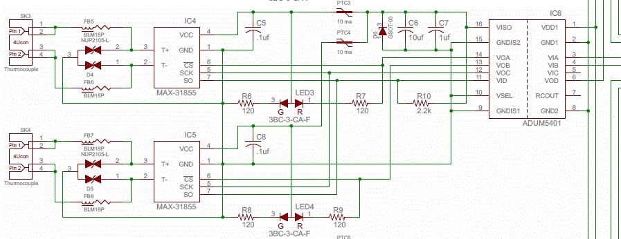
The chip checks for a grounded or supply tided probe condition and has error bits for it... So, I figure something like this may work ok.. This type of ISO chip also supplies power for the converter IC's.... I can even check if "power is ok" from my end.. On the larger system, I will be using the LTC2983 IC, which uses a deferential type setup, and doesn't need the isolation... This cheaper, 2 channel gauge is another bag of knots to untie... |
||||
| The Back Shed's forum code is written, and hosted, in Australia. | © JAQ Software 2026 |
