
|
|
Forum Index : Microcontroller and PC projects : New York Geothermal Control Architecture
| Page 1 of 2 |
|||||
| Author | Message | ||||
| Paul_L Guru Joined: 03/03/2016 Location: United StatesPosts: 769 |
I find that I need the aggregate wisdom of all of you concerning the general architecture of the control system for my geothermal heating system. A brief description of the system is needed. Heat is absorbed from the earth by a large heat exchanger buried 10 feet down in my yard. This heat exchanger consists of 6000 feet of 3/4" HDPE pipe and the 300 feet of 2" HDPE pipe. An anti-freeze mixture is pumped through this pipe and then through a plate type heat exchanger (the evaporator) where the heat is transferred to liquid Freon causing it to boil into gaseous Freon. This Freon gas is then compressed by an 8 kW Freon compressor. This high-pressure Freon gas than is rooted to a second plate type heat exchanger (the condenser) where heat is transferred to water causing the high-pressure Freon gas to condense into liquid Freon. This liquid Freon then passes through an expansion valve, which reduces the pressure and the boiling temperature of the Freon, and then returns, as a liquid, to the evaporator. The heat has now been transferred to water in the evaporator, which is then pumped to an insulated storage tank. Romance thermostats located around the house then operate distribution pumps which pump the warm water from the storage tank to convectors, heated floor slabs, or air handlers with blowers to warm the house. The internal water passages in the plate type heat exchangers consist of Chevron patterns which are pressed into sheets of stainless steel 0.032" thick. There are 40 of these thin plates brazed into a stack about 4" thick creating 400 water passages which are about 0.068" thick and 0.5" wide. The Freon compressor is powerful enough to freeze the water in these tiny water passages into solid ice in seconds which would physically destroy the heat exchanger. The Freon compressor must be stopped quickly when the temperatures in the plate type heat exchangers approaches the freezing point of the antifreeze mixture. Processor Tasks. The processor must measure the temperatures of the circulating Freon and water, using DS18B20 bandgap sensors fastened to the copper piping, at the eight entry and exit points of the plate type heat exchangers in order to control the Freon compressor. These Freon compressor control cycles must be repeated every few seconds, without fail, whenever the Freon compressor is operating. The other tasks that the processor must do cannot be permitted to interfere with these repetitive measurements and control calculations. The processor must measure air temperatures in various rooms of the house and outside of the house, using DS18B20 sensors, in order to control heat distribution to the different zones in the house, and to control whether he is being pumped into the house in the winter, or out of the house in the summer. The geothermal heat pump is bidirectional. These measurements and calculations cannot be permitted to slow the repetition of the Freon compressor control cycles. The processor must display the operating status of the entire system and the temperatures observed in various places, without slowing the repetition of the Freon compressor control cycles. The processor must accept user input, via a touch sensitive screen, of various temperature limits used in the control calculations, without slowing the repetition of the Freon compressor control cycles. The processor must create a data log of the temperatures it has observed and the control decisions it has made repetitively every few minutes, without slowing the repetition of the Freon compressor control cycles. The processor must provide a way to either transmit this data log to a PC, or permit removal of a camera card for a few minutes for the purpose of copying files to a PC, without slowing the repetition of the Freon compressor control cycles. One uM+ or 2 uM+ processors? The one task that can obviously interfere with the continuous repetition of the Freon compressor control cycles is user input. I believe that it may be possible, using interrupts, to accept user input from the touchscreen without slowing this repetition very much, but I am not familiar enough with the recent additions to MMbasic to be sure. Alternatively, a second processor, probably on the same board or on a daughter board, could be dedicated to the task of displaying data, accepting user input, and repetitively building the data log file. This processor could wait around all day for the slow speed human to press the screen again without interfering with the compressor control loop. But this would require the main processor to continuously send all of its data and control decisions to the display processor, and it would require the display processor to send user changed operating parameters back to the main processor. This would require both processors to do a lot of handshaking and checking for data from the other processor, and I don't know how this could be done. Is there a way to do this with one processor using interrupts? If not, how would I repetitively transfer all of this data back and forth between two processors? |
||||
| panky Guru Joined: 02/10/2012 Location: AustraliaPosts: 1130 |
A few thoughts Paul - with the cost of 2 or even more 'mites being insignificant to the overall cost, for critical processes like control of the Freon compressor, I would dedicate a 'mite to that task. You could then ACK/NAK (handshake protocol for simple comms) between that 'mite and a central 'mite to do the control, logging and user interface. As a start, I would try to identify the processes in a flow chart form. If you could post that then forum members could more easily assist. Great project and I look forward to watching progress - happy to help if I can, Doug. ... almost all of the Maximites, the MicromMites, the MM Extremes, the ArmMites, the PicoMite and loving it! |
||||
palcal Guru Joined: 12/10/2011 Location: AustraliaPosts: 2039 |
I am sure that the evaporator temperature can be stopped from dropping too low and thus freezing by fitting a pressure control to the suction side of the compressor. As the evaporator temperature drops so too does the back pressure. I am surprised the unit is not fitted with one already as it is standard practise. ( I am a refrigeration mechanic.) Paul. "It is better to be ignorant and ask a stupid question than to be plain Stupid and not ask at all" |
||||
| Paul_L Guru Joined: 03/03/2016 Location: United StatesPosts: 769 |
@Paul. Copeland does install a low pressure limit in the compressor which turns it off, but it requires a removal of all power in order to reset, but it is set lower than is useful. By the time it trips the exchanger has frozen. I have not been able to find pressure sensors which are as precise and reliable as the DS18B20 sensors which will see the boiling temperature of the Freon after the expansion valve. I also do not want to breach the Freon system directly if I can help it. The liquid line tubing is 7/8" OD. Thanks for your thoughts. |
||||
| Paul_L Guru Joined: 03/03/2016 Location: United StatesPosts: 769 |
@Doug. I like the idea of two 'mites with one dedicated to controlling the Freon compressor itself, and I'm working on some broad pseudo code. How do I implement the I/O lines without causing one or the other 'mite to pause its program? I don't see either direct I/O pin polling commands in MMBasic or a dedicated input storage register in the PIC processor. Can I just set an output pin high on the first 'mite and then somehow check the state of the associated input pin on the other 'mite thus implementing a "can I talk line"? Paul Paul. |
||||
| Geoffg Guru Joined: 06/06/2011 Location: AustraliaPosts: 3363 |
I agree with panky. Use one processor running a simple program to monitor the Freon compressor. With a simple program you can be assured that it will be reliable. Then use another for display, logging, etc. This might crash due to programming errors, input errors, etc but the first processor will be still running and protecting the critical section. Geoff Geoff Graham - http://geoffg.net |
||||
CircuitGizmos Guru Joined: 08/09/2011 Location: United StatesPosts: 1427 |
Sounds like using multiple microcontrollers is the way to go. One architecture aspect I would mention that may not be obvious if not specifically stated: The microcontroller nearest to the sensors should be making all of the real-time decisions. It should be able to run completely on its own - it only reports status to the other micro, or accepts changes to set points. That way if the logging/display microcontroller gets busy, or the communication line is lost the sensor microcontroller doesn't sit around and ask "Hey my temp just dropped 4 degrees, what do I do? Hello? Hello?" The sensor micro should be able to make decisions without the other micro. Identifying all conditions, including all out of bound conditions, is important in any control situation. Micromites and Maximites! - Beginning Maximite |
||||
mikeb Senior Member Joined: 10/04/2016 Location: AustraliaPosts: 180 |
Hi Paul, I think I've got the included drawing right based on your functional descripton. My background is refrigeration, air conditioning and building management systems. Definately two MM+'s with 7" touchscreens. One for the left side of the storage tank and one for the right side. Right one could have RTC, for time scheduling, an SD card for data logging and an RF module to suck out the data, probably in csv format ready to slot into an Excel spreadsheet. If your data is setup correctly in an array it will be a simple matter to transfer the array from the left MM+ (condensing unit) to the right MM+ (indoor coil control) onto an SD card and then on to your PC via RF. The right MM+ would also look after the room Temp sensors and associated coil pump control. I can see the graphics now !!!!! The left one would look after the condensing unit. I would start and stop the unit based on the temperature of the water as indicated by the sensor located between the storage tank and the heat exchanger pump (bottom of tank in drawing). The condensing unit would not be allowed to start until the flow status of BOTH heat exchanger pumps was proven. Would recommend flow switches for this task. I would ditch the expansion valve if you can, and fit an electronic expansion valve, that way you could precisely control superheat. Cheap stepper motor drivers are readily available (do a search for Pololu) and could be hooked up to a PWM output, or pulse an output in conjunction with an interrupt, of the MM+ to output the desired number of pulses required to maintain superheat. You'll notice I have included enough temp\pressure sensors to achieve this. Otherwise keep the TXV but the sensors are probably still handy. The pressure sensors could provide for high, and low, pressure cutout. Likewise for the Temp sensors. Setup a serial comms link between the two and you'll have your very own BMS. Geoff has included enough interrupt sources to do ALL that you require......and some. 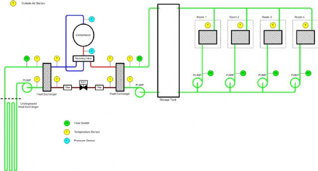
There are 10 kinds of people in the world. Those that understand binary and those that don't. |
||||
| Paul_L Guru Joined: 03/03/2016 Location: United StatesPosts: 769 |
Hi Mike, Thanks for your reply. Your drawing is almost exactly what I'm dealing with and your suggestions are well thought out. I really don't want to open up the freon system again. I had to replace the reversing valve several years ago and it was a hassle to pump it down again. I doubt that I will switch to an electronic expansion valve. I have measured the evaporator superheat several times and it is always about 12�F so I think the TEV is functioning well. I would like to be able to measure the freon pressures but I have been unable to find pressure transducers which seem reliable and accurate. I think that observing the temperatures into and out of the compressor will probably suffice. The Copeland scroll compressor has internal high and low pressure limit control so I'm not worrying about the compressor being damaged. I'm also not too worried about slugging liquid into the compressor since the scroll design is inherently resistant to damage from liquid ingestion. My principal worry is preventing sudden freezing of the plate type exchangers. I have been unable to find any water flow sensors which don't produce a lot of head loss and which I regard as reliable. The yard pump I'm using, the Bell & Gossett PL-36, provides a flow of about 28 gpm = 224 lbs/minute = 13,440 lbs/hour. A 5�F change therefore produces 67,200 btu/hr which is just about the heat requirements for this house at 0�F outside. As an alternative to a water flow sensor I have been thinking of using two water pressure sensors before and after each water pump. If the head produced by the pump is in the right range the water must be flowing. I'm not sure about your division of the tasks between the two uMs. I don't believe that the control of the distribution pumps will take much processor time. I would probably plan on including that code in the primary uM code. I think it would be best to keep the user input code by itself in the second uM. Maybe I can work out a way of using interrupt techniques to detect user input and manage to do the whole job in one uM. The additional complexity of having two uMs talk to each other, with all of the handshaking required, might be more difficult than watching for interrupts from the touch screen. I don't believe I can use the 430 MHz RF modules which are commonly available in the states. The FCC has a 10 mw limit in that band. If I use two uM processors I think that they will have to be hard wired together. I had just about concluded that I would try to include all the data in an array before reading your reply and I'm glad to see that you think that would be best. Paul |
||||
| Paul_L Guru Joined: 03/03/2016 Location: United StatesPosts: 769 |
I agree that the main control loop can't be stopped by user input. Do you think that I can use Geoff's interrupt sensing to set flags when the user touches the screen and then process the keypress later? |
||||
| bigfix Senior Member Joined: 20/02/2014 Location: AustriaPosts: 132 |
I use an Industrial Flow Sensor IFM 1000 for my ground water circuit to the heat exchanger they are normally rather expensive, but you can get them in ebay often i.e. IFM 1000 It works by tiny temperature differences in the probe tip Basically you train it to a known good flow and then it switches at set thresholds It does not give any absolute value back I used paddle sensors in the past, they lasted 20 years originally now the exactly same sensor lasts 2 years - improved design... One problem with the plate heat exchangers is, that you can get pockets of colder water, which freeze early. So you should not go close to freezing I run plain groundwater through the heat exchanger, a glycol mix on the secondary side - so two degree centigrade is my set limit on the glycol side I would vote for a real simple additional protection with a plain thermostat at the heat exchanger, besides all the intelligent stuff... |
||||
| mikeb Senior Member Joined: 10/04/2016 Location: AustraliaPosts: 180 |
Hi Paul, My suggestion for the RF module (bluetooth, wifi, whatever) was purely for getting logged data, from the MM+, onto your computer. I would definitely set up a hardwired RS485 serial connection between the to MM+'s. I envisaged one of the touchscreen\MM+ combinations to be inside the house. Looking at your pipe sizes a DP switch across the pumps would definitely be the go. I did a lot of compressor retrofits in a data centre a while back. The failure mode, due to liquid floodback, was a destroyed 'top end' bearing due to the liquid washing out the oil in this bearing. You could indeed do the whole installation in one MM+. I just like the idea of a touchscreen, for users, inside the house and a touchscreen at the equipment which is likely somewhere else. There are 10 kinds of people in the world. Those that understand binary and those that don't. |
||||
| mikeb Senior Member Joined: 10/04/2016 Location: AustraliaPosts: 180 |
Hi Paul, The problem won't be running out of internal resources, program\variable space, interrupts etc, but running out of external I|O pins. The MM+ is more than fast enough to do what you want. If you split your system up down the middle of the storage tank then you can logically divide it up. Your condensing unit side MM+ needs to know too things from the other side - when to run and what temperature water to supply. There are 10 kinds of people in the world. Those that understand binary and those that don't. |
||||
| Paul_L Guru Joined: 03/03/2016 Location: United StatesPosts: 769 |
OK guys, I'm stumped. I can't figure out how to make a sandwich and put it into a box. How can I put together a sandwich consisting of 1. a MAIN uM+ board handling the sensor reading and computation loop plus 2. an interface board with power supply, relay drivers, and connectors plus 3. another USER uM+ board handling the touch screen code plus 4. a 7 inch touch screen display, 5. and then enclose the whole mess in a box with the screen on one side and I/O connector plugs on one edge which can be mounted in a wall. A sandwich with a uM+ board on the back of a display is easy using spacers and female headers. When you try to add the other two boards behind the first uM+ board it comes unglued. I need to be able to have connection headers on both sides of the display uM+ board so that the display connects to one side and the interface board to the other. The interface board also needs headers on both sides. |
||||
| Paul_L Guru Joined: 03/03/2016 Location: United StatesPosts: 769 |
OK guys, I'm stumped again. I've got most of the code mapped out but I can't figure out a simple way to get the two uM+ processors MAIN and USER talking to each other. MAIN runs a loop which process sensor inputs, sets relays, sends data to USER, receives settings from USER, and builds a log file of the data and relay settings. The MAIN loop will take less than 3 seconds to process and it has to repeat immediately without being delay waiting for USER to respond. USER runs a loop which receives data from MAIN, displays this data, and sends changed settings to MAIN. USER will react to interrupts from the touch screen to change settings but the human interrupts can't be allowed to delay the receiving and sending data with MAIN which would delay the loop in MAIN. There has to be some handshaking and synchronization between MAIN and USER. The MAIN code can set a flag indicating that it's time to talk. USER must immediately acknowledge the flag then MAIN has to immediately send an array to USER and USER has to immediately send an array to MAIN. I have looked through the libraries and the threads here. I haven't found any previously implemented code which can provide this kind of timed communications window. Should I try to do it by letting MAIN's loop speed, (which will be dependent largely on the speed of the 15 or so DS18B20 temperature sensor replies), determine when the communication window starts, or should I try to do it by establishing a fixed repetitive time, say 3 seconds, for the communication window to start? |
||||
plover Guru Joined: 18/04/2013 Location: AustraliaPosts: 306 |
My suggestion, do not sandwhich the lot. My understanding is you may have plenty of room for an indutrial greade box. Have a basebord pcb where your modules plug in, this way you have easy access to replace any module you like. Input/ouput connectors to be placed at the edge of the board. Swing out cover/door where you mount what you need. Don't make the box too small , you want to have access for the electrician or yourself to be able to trouble shoot, probaly with a small laptop sitting on a swing out shelf. On the base board (make it a big pcb) which should hav suitable number of isolation links, these really can not be decided until the complete circuit diagram available Have spares of everything, including the base board, which with a complete set of spares fitted can be used for trouble shooting a problem off line if need be. You can replace the whole working back board at least get running again. 
|
||||
| Paul_L Guru Joined: 03/03/2016 Location: United StatesPosts: 769 |
The MAIN uM+ will be reading a maximum of 17 DS18B20 sensors with each sensor having its own pin. (Trying to chain sensors on one wire doesn't make sense here to save wire because the sensors are spread in all directions from the central point where the processor will be.) The MAIN uM+ will also be controlling a maximum of 14 high power relays, preferably using 14 dedicated output pins. The MAIN uM+ will also need two handshaking pins and two serial I/O pins to talk to the USER uM+. That seems to be a total of 35 I/O pins. Which available assembled uM+ boards will provide this many pins? There is a possibility that I could send a control string, using an I2C protocol, to a PICAXE which could then split up the string and control the output relays. This could reduce the pin count from 35 to 22 pins but it would increase the complexity of the I/O interface board. There is also a possibility that I could use an I2C extender based on an NXP P82B715TD I2C bus extender and a Microchip MCP23008-E/P-ND I/O expander but this would probably be less satisfactory than using a PICAXE. Do you think I will need to use an I2C expander or can I find a uM+ implementation which will work? |
||||
| Paul_L Guru Joined: 03/03/2016 Location: United StatesPosts: 769 |
It sounds like you want me to go back to wirewrapping the backplane main frame for an IBM 360 with its plug in modules. I agree that it would make troubleshooting easier and replacing failed modules easier, but I'm reluctant to spread the thing all over a square foot of real estate. My quarter century of experience on Boeing aircraft tells me that most of the problems that develop from modern solid state gizmos come from the interconnections and wires. I'm trying to keep it as compact as possible. If it turns out that the sandwich stack is impractical then I'll have to figure out a horizontal assembly with boards next to one another, but I don't think I'll go as far as a big mother board. I assume that's what you mean when you say "baseboard". What is a "baseboard" in OZ speak? |
||||
| mikeb Senior Member Joined: 10/04/2016 Location: AustraliaPosts: 180 |
Hi Paul, I wouldn't use a 'sandwich' construction as it is far too difficult to fault find. Surely you have space to use a bigger enclosure. Have you drawn this project concept out on paper or are you working from your head ? A picture is worth a thousand words. If you would like to send through a rough layout of your installation, and a desired I\O list, I can help you with a drawing and system design concept. I do not profess to have all the answers, when it comes to programming, but I have a good understanding of MM resources, and system requirements, to help you with a 'functional, and serviceable, system design. Use the TEMP START function, and a 'tick' interrupt routine, for your 18SB20's. If you are not comfortable with multiplexing the I\O using latches, and having to change pin direction on the fly, then use multiple MM's and connect together with a serial link. The first data packet can be the address of the module you wish to update. The serial comms function makes use of an interrupt and a configurable data buffer so it shouldn't be a problem. Break your project up into logical\manageable segments. Have a look at page 5 of the MMBasic Ver 5.1 manual. It lists I\O capability of all devices. Mike B. There are 10 kinds of people in the world. Those that understand binary and those that don't. |
||||
Grogster Admin Group Joined: 31/12/2012 Location: New ZealandPosts: 9985 |
One standard 28-pin DIL or SOIC MM chip controlling the freon compressor and sensors(17x 18B20 sensors + COM1), and one MM+ 64-pin controlling the screen and input etc. With the MM and MM+'s built-in serial port buffer, it can be setup so that it can hold on to any data that is sent to it, and the main loop can check the buffer - if there is something in the buffer, it can suck that data out, send acknowledge to the 28 pin MM, and process the data at that point - leaving the 28-pin MM to carry on monitoring the sensors. The 28-pin MM can use it's serial port in the same way, and as part of the loop of looking at sensors, it just needs to check the serial port buffer once per loop - if there is something there(like a request for info), it loops to that and does that, then returns to the main loop. I expect that could all easily be achieved inside of the 3 seconds mentioned earlier, probably even with the 28-pin chip throttled back on speed. If you use COM1, all the data buffering is done for you in the background by the PIC32 hardware UART, so you only need to pass the instruction, then move back to looking at the sensors. The PIC32 will take care of placing the data to send into the outgoing buffer, and storing anything received in the receive buffer. This means that the code is not hanging around waiting for data to arrive or to send - it does all that for you, and you can get on with something else. 
Unless I am missing something(and that is quite likely!), you would not even need handshaking lines - you just send the data, and the buffers will look after sucking the data from the other MM into the buffer at each end, then you only have to check the buffer with the LOC function to determine if there is anything there for attention. ...perhaps I am missing something though........ Smoke makes things work. When the smoke gets out, it stops! |
||||
| Page 1 of 2 |
|||||
| The Back Shed's forum code is written, and hosted, in Australia. | © JAQ Software 2026 |
