
|
|
Forum Index : Microcontroller and PC projects : Checking Limits
| Page 1 of 2 |
|||||
| Author | Message | ||||
| Phil23 Guru Joined: 27/03/2016 Location: AustraliaPosts: 1667 |
Hi all, I'd like to check the limit switches on a couple of motorised ball valves & looking for suggestions. Each valve simply has a SPDT limit switch, so 4 wires back to the micro would do it, but I'd like to get it done on a single wire. Partially to save on IO pins & also to save on cable cores. If I did everything the simple way I'd be needing about 12 cores so far. At the moment I'm using 6. What I'm thinking is along the lines of the Transmission position switch in my car. It's basically a 7 position rotary switch with a bunch of resistors in series to create a voltage divider. The contact slider is designed so the is no nul value between positions. (Yes, I've pulled mine apart.....). What would be the best way to wire these 2 SPDT switches to get a similar resistance scaled output that and be read? Something that needs to be taken into account is the switch being in the in between position, as the valves take roughly 10 seconds to change position. A 4 pole rotary switch would be easy, there's either a pole connected, or the Nul between positions. With the 2 limit switches, either or both of them could be in the nul position. Thanks Phil |
||||
TassyJim Guru Joined: 07/08/2011 Location: AustraliaPosts: 6543 |
I think this is what you are after 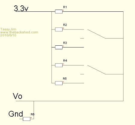
With the correct values, you can cater for all 9 possible combinations. These values (in k ohms) R1 100
R2 22 R3 2 R4 10 R5 1 R6 1 gives 2.856018883
2.972972973 2.049689441 3.126614987 3.267326733 2.185430464 1.605484299 1.641791045 1.314741036 these 9 voltages. There will be better choices of resistors. Open circuit cable gives 0 volts. Jim VK7JH MMedit |
||||
| Phil23 Guru Joined: 27/03/2016 Location: AustraliaPosts: 1667 |
Thanks Jim, Will play with the values. Not getting very accurate voltages off the little solar panel I'm using to read the sun intensity at the moment. 410-550 I've got a 10 Ohm load across the panel & it's maximum output when the sun is vertical is around 1V. Seems like the sun is usable for water heating once the voltage is above about 300mV. MicroMite Vs Meter Voltages are a bit like this:- [Code] True Voltage MM Reading 300mV 200mV 500mV 390mV 640mV 500mV [/code] Would like to add an external reference like in this thread by pmather, but not quite clear on how it is implemented. Connections etc. Currently just reading the voltage off Pin 4. Would an LM336 2.5 volt reference be the right thing to use? Considering I'm looking for say 0-1100mV. Don't need precision for this, just linearity. (Do want to use the same for precision on the thermistors I need to read though). I get a little lost on what connects where & which of the "Vref+ and/or Vref- and/or AVdd" would apply in my case. I get the function returns an integer 0-1023, but don't quite have my head around the rest. [Code] The readADC routine takes two parameters, the pin number to read and the mode. All relevant pins (pin to read and reference pins) must previously be set as analogue inputs using SETPIN n,AIN The routine returns the actual ADC count (0-1023), you then need to convert this to a voltage based on the actual values of Vref+ and/or Vref- and/or AVdd as applicable. So if Vref+ is 2.048V and Vref- is 1.024V and readADC returns 255 in mode-3 then the voltage is 1.024+ 255/1023*(2.048-1.024) = 1.279V [/code] Thanks Phil |
||||
mikeb Senior Member Joined: 10/04/2016 Location: AustraliaPosts: 180 |
Hi Phil, How far are the valves from the MM ? Using an analogue input will be prone to noise pickup. The 1K0 resistor (R6) Jim suggests will at least keep a low impedance at the input. Keep in mind that you are running an antennae out into the field. Be careful of cable run. Route away from all sources which are likely to induce a voltage into the cable. Filter your input signal in hardware, and software, and use clamp protection at the input. Are you really that short of pins ? There are 10 kinds of people in the world. Those that understand binary and those that don't. |
||||
| TassyJim Guru Joined: 07/08/2011 Location: AustraliaPosts: 6543 |
The micromite can resolve about 3.2mV (3.3 / 1024) If you only have 1 volt to play with, you are getting down to 8 bit precision instead of the full 10 bits. I used a voltage reference such as the LM336 in my data acquisition setup. It was connected to an analogue pin and any difference from 2.5V was used as a correction factor for the other readings. With the limit switch voltage divider, if you are using the same supply as the micromite, there is no correction needed, it's just a ratio. Jim VK7JH MMedit |
||||
| MicroBlocks Guru Joined: 12/05/2012 Location: ThailandPosts: 2209 |
If the valves are located relatively close together but far away from the MM you could generate a frequency that can be measured by the MM. A small R/C circuit would be enough. Microblocks. Build with logic. |
||||
boss Senior Member Joined: 19/08/2011 Location: CanadaPosts: 268 |
@Phil try this 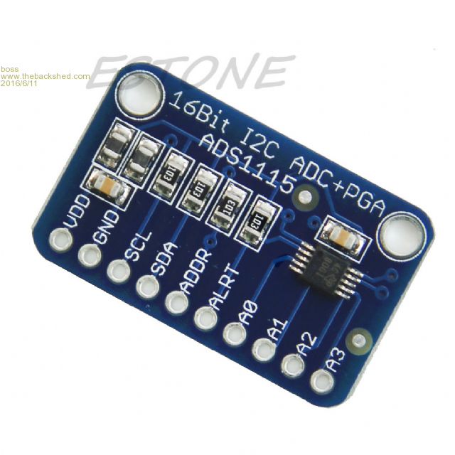
ADS1115 4x 16bit A/D, I2C, ~$3.50 on Ebay. Bo |
||||
| matherp Guru Joined: 11/12/2012 Location: United KingdomPosts: 11605 |
What don't you understand? To read a value between 0 and say 1.25V use mode 1 (mode=1, Vref+ external and Vref- is AVss/GND ), i.e. connect a 1.25V source to the Vref+ pin (just use a voltage divider off the 3.3V if this is accurate enough for your purposes). The vref+ pin is pin 2 on a 28-pin part and pin 19 on a 44. Both the pin to be read and the vref+ pin should be set as AIN Then to convert to a voltage just scale the count value by 1.25/1023 |
||||
| Phil23 Guru Joined: 27/03/2016 Location: AustraliaPosts: 1667 |
So to get the most accurate readings from the thermistors in the heat pump unit, I could take the output of an LM336 to pin 2, the thermistor divider circuit to another & then scale by 3.25/1023. The difficult part about understanding it probably stems from not completely understanding in layman's term the meaning of the terms like Vref+, Vref-, etc. Re using a Voltage divider to apply 1.25V to Pin 2. So, this would result in me spreading the 1023 steps of resolution over 0-1.25 volts, creating resolution steps of 1.25/1023=1.2mV, compared to what I'm currently doing and only reading 1.25/3.3*1023=387 steps or resolution over the same range, with 3.2mV resolution. Phil |
||||
| Phil23 Guru Joined: 27/03/2016 Location: AustraliaPosts: 1667 |
|
||||
| Phil23 Guru Joined: 27/03/2016 Location: AustraliaPosts: 1667 |
Understand the limit switch voltage scenario/voltage divider. It's the thermistors that are giving me issues. I've got one attached along side a DS18B20 & at times they agree realy well, but on occasions the thermistor temp drifts off. Pretty sure its attributed to that Backpack's 3.3V supply that is still less than perfect, but haven't sorted that out completely yet. Likes to sit around 3.45, but can be anywhere from 3.25 up to 3.65. Can't see a pattern, & have so far only changed the 2 10�F caps but not the reg. Have both MCP1700's & AMS1117's here & contemplated whether the AMS1117's might be better due to their higher current rating. Not a straight pin swap though. I know my ancient Fluke 77 (1985) isn't off the mark, it's sat for a few times on an AD584L voltage reference, & the 5 volt reference sits rock solid on 5.05V on the meter. Accuracy should be 0.3%+/- one digit so 5.035 + one digit would be in tolerance. Cheers Phil |
||||
| mikeb Senior Member Joined: 10/04/2016 Location: AustraliaPosts: 180 |
Don't have time to sort out that bloody quote button. Maybe you could tell me how to use it. 10m no problem. I remember seeing one of your posts regarding DS18B20's. Why don't you use them instead ? They certainly have sufficient measuring range. Use the 8 core shielded. Remember to connect the shield at ONE end only otherwise you will set up a 'shorted turn' which is ideal to induce spurious signals into. Think of how a transformer works. The UTP cable is for differential data networks. That is why it is of a twisted pair construction. Ideal for ethernet and RS485. Besides, it is designed to be terminated with an IDC crimp plug. Not stripped and wired to a terminal. You only have to 'knick' the copper conductor (solid core variety) and the conductor will fail at that point when you bend it. Put a 10uF tantalum cap in parallel with your 100n cap. You could try to work out the 'passband' performance buy I tend not to bother. The temperature should be a relatively slow moving variable and it should not be detrimental with the time constant of the 10uF cap and a 'lowish' current limiting resistor (4k7 max). Make sure this limiting resistor is on the MM side of Jim's 1k0 to ground otherwise you will set up a voltage divider. You will set up one with R6, in series with R1, in his circuit but you'll just have to account for it in calculations. The prime need is to protect the PIC pin from damaging transients. For clamping I generally use a device generically named as a 'Transorb'. Google that and you'll get plenty of hits. These are, in essence, a very fast zener diode. Get bi-directional ones and they will protect you against most transients (+\-) you are likely to experience. If you get a lightning strike then you will have bigger concerns than a damaged PIC  . Go to Harvey Norman and they will try to sell you a surge protector, as always . Go to Harvey Norman and they will try to sell you a surge protector, as always  , ,
Thermisters are good, cheap sensors but are nothing like linear in their output. I note your reply to TassyJim re measuring a DS18B20 alongside a thermister. DS18B20's are linear across the entire range. Thermister's are not. Matherp did a great piece on using them correctly utilising the well known Steinhart-Hart equation. Follow this link -Fun with Thermistors. Unless you wish to retain existing equipment I would ditch the thermisters and use DS18B20 assemblies readily available on eBay. Why not have a dedicated MM, up at the equipment, just to perform tasks associated with the equipment, and run a serial comms connection down to another MM used for display, RTC etc and user input ? I like to 'Divide and Conquer'. I don't like having to deal with 'low level' analogue signals if I don't have to. Circuit layout becomes critical. The use of a stable reference becomes paramount. Although there are neat tricks for autoranging to maintain resolution. See latest SC for example. I also don't like having to multiplex an I\O buss, use latches etc when it simply isn't necessary. MM's are cheap as chips. There is nothing wrong with 'Distributed Intelligence'. It also cuts down on the cable run between the equipment and the user. Power and Comms. There are 10 kinds of people in the world. Those that understand binary and those that don't. |
||||
| Phil23 Guru Joined: 27/03/2016 Location: AustraliaPosts: 1667 |
|
||||
redrok Senior Member Joined: 15/09/2014 Location: United StatesPosts: 209 |
Hi Phil;Solar PV cells can do a fairly accurate job of measuring the suns apparent intensity. But there are some constraints. A PV cell is essentially a "current source". This current is highly linear with the incoming light intensity. However, this linearity is only when the cell voltage is near 0 volts. As the voltage across the cell is allowed to increase some current begins to flow through the intrinsic P-N junction of the cell. At the extreme, all the current is "self consumed" by its junction at 0.5V to 0.7V. Also PV cells generally have a lot more "Leakage Current" than most diodes leading to more non-linearity at higher voltages. Anyway, the "best solution" is to use an Op-Amp in a "current to voltage converting" circuit which forces the voltage to 0 volts. But a "Practical" circuit would be one that kept the voltage less then about 0.2V for a silicon cell using a shunt resistor as you are doing. Apparently 10 ohms is a bit to large. I would guess that about 2 ohms would get the voltage down to 0.1V at an influx of 1000W/m^2. redrok |
||||
| Phil23 Guru Joined: 27/03/2016 Location: AustraliaPosts: 1667 |
I presume you are referring to a single cell in the panel as opposed to the whole cell? I did get on the roof yesterday & remove the resistor.... Open circuit voltage was useless, as I already knew, about 2400mV with the sun rather low in the afternoon. from memory I think maximum OC voltage is 2.8-2.9. I was figuring on trying alternate values at the controller end, (easier to poke a resistor in the breadboard, than soldering on the roof). Tried 27 ohms as a starter & it gave a good figure in my head. I'm not looking for accurate watts/m� at this point, just a "Sun is bright enough" variable. Don't intend to make rash decisions with this like pump on/off the moment it sees a cloud, but take it into consideration with other inputs. |
||||
| robert.rozee Guru Joined: 31/12/2012 Location: New ZealandPosts: 2541 |
regarding the original question: motorized valves with limit switches (2 per valve), with approx 10 seconds between limits while valve is in transit; i'd suggest the following: 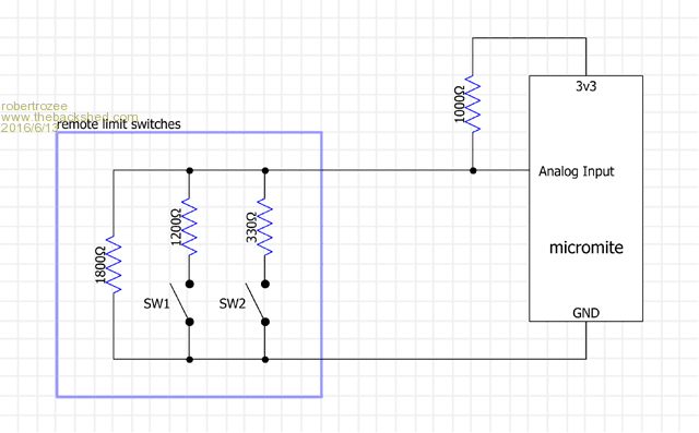
with both SW1 and SW2 open, about 2.1v will be present at the analog input, with SW1 closed there will be about 1.4v, with SW2 closed there will be about 0.7v. under fault conditions of the wiring from the micromite open-circuit there will be 3.3v at the analog input, while a short will result in 0v. these voltages are what the micromite 'believes' are present, and are independant of Vcc. no external reference or precise Vcc should be needed. the wiring 'cost' is a twisted pair to each valve, and 1 analog input pin per valve on the micromite. i would recommend against trying to encode more than a couple of switches per analog input. it is also a very good idea to have the motor travel shut down by a seperate set of contacts on the limit switches - i presume this is built into the motorized valve design? another safety feature is to monitor the motor current. the below spreadsheet contains the resistor value calculations: 2016-06-13_121906_resistor_values.zip cheers, rob :-) |
||||
| Phil23 Guru Joined: 27/03/2016 Location: AustraliaPosts: 1667 |
At this point now; motorised ball valve installed. Courtesy of Teenager on School holidays... 
It's 12V DC, polarity reversed to change direction. SPDT limit switch. |
||||
palcal Guru Joined: 12/10/2011 Location: AustraliaPosts: 2039 |
Instead of using a solar panel for sun intensity could you use a LDR Paul. "It is better to be ignorant and ask a stupid question than to be plain Stupid and not ask at all" |
||||
| Phil23 Guru Joined: 27/03/2016 Location: AustraliaPosts: 1667 |
Yes have thought of that & have a couple of LDR modules here, as well as some LUX sensors. One thing the Solar panel does reasonably well is compensate for low sun angle in the afternoon. Not needing anything super accurate & will refine things with time. Cheers Phil. |
||||
| robert.rozee Guru Joined: 31/12/2012 Location: New ZealandPosts: 2541 |
use something like this: setpin 2, AIN
do v=pin(2) if v<0.4 then print "short to ground" elseif v<1.1 then print "SW2 closed" elseif v<1.8 then print "SW1 closed" elseif v<2.7 then print "both switches open" else print "open circuit" endif loop note that the case of both switches being closed at once is not distinguished from just SW2 closed, but this situation could only occur if there was a mechanical failure in one of the switches. cheers, rob :-) |
||||
| Page 1 of 2 |
|||||
| The Back Shed's forum code is written, and hosted, in Australia. | © JAQ Software 2026 |
