
|
|
Forum Index : Microcontroller and PC projects : MM+, Explore 64 and Explore 100
| Page 1 of 6 |
|||||
| Author | Message | ||||
| Geoffg Guru Joined: 06/06/2011 Location: AustraliaPosts: 3362 |
This is a heads up on the introduction of the Micromite Plus, the development of which was influenced by many here. It will feature in three articles in Silicon Chip magazine starting with the August issue. Also featured will be the Explore 64 which most people know about and the Explore 100 which is a new board. The Explore 100 is a 100-pin Micromite Plus on a PCB which is designed to fit on the back of a 5" LCD panel. Like the Explore 64 the PCB was designed by Grogster (thanks Grogs) and is a marvel of design being a four layer board. It has two sockets for click boards plus USB, RTC, console and PS2 keyboard connectors. Grogster will be selling both boards on his website at: http://www.rictech.nz/micromite-products Even better, he will be offering a version of the Explore 100 with the SMD components (there are four) already soldered and the micro programmed with V5.2. All the other components are standard through hole parts and easy to solder. So people with poor eyesight will not have an excuse! I will update my website when I return from overseas but in the meantime I have made a video describing the MM+ and both boards. This one is shorter and more succinct than my previous effort but I still need to improve my video expertise. You can see it at: https://youtu.be/j12LidkzG2A Geoff Explore 100 features: 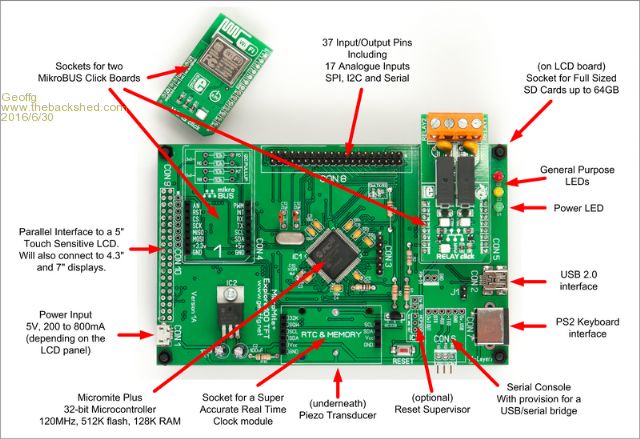
Geoff Graham - http://geoffg.net |
||||
TassyJim Guru Joined: 07/08/2011 Location: AustraliaPosts: 6533 |
No need to improve the video expertise Geoff, It stands out from most of the out-of-focus, handheld ones that are out there. Jim VK7JH MMedit |
||||
palcal Guru Joined: 12/10/2011 Location: AustraliaPosts: 2039 |
Nice looking board Grogs and there certainly is a great selection of Click Boards. Looking forward to it. Paul. "It is better to be ignorant and ask a stupid question than to be plain Stupid and not ask at all" |
||||
kiiid Guru Joined: 11/05/2013 Location: United KingdomPosts: 671 |
This one is very good indeed. I am going to get one of these for sure, for experiments. http://rittle.org -------------- |
||||
| JohnS Guru Joined: 18/11/2011 Location: United KingdomPosts: 4332 |
For the Explore 100: I'm guessing the circuit diagram will be available later? Exactly which CPU is it please? This thread won't be found by google etc on searches for it (the CPU) unless it's stated. John |
||||
Grogster Admin Group Joined: 31/12/2012 Location: New ZealandPosts: 9973 |
Hi folks. 
@ Palcal: Prior to Geoff telling me he wanted to design for those Click boards, I had never heard of them, but yeah, there are lots and LOTS of them, which is a real bonus, and should allow people to easily and cheaply expand on what the Explore-100 can do. @ JohnS: The chip used is the PIC32MX470F512L-120I/PT. 12mm package, 100-pin TQFP, 0.5mm pin-pitch. This board is not yet up on my website, but it will be in the next day or so. I will be offering a blank PCB for those who want to assemble everything themselves, and a full-kit including everything to make the E100 board, but NOT the LCD, as that is something of a personal choice. The full-kit will have the SMD pre-mounted and pre-programmed as Geoff says. EDIT: It should also be noted that in the photo, that is the 1A prototype, and the 1B boards use a standard DC socket for the power, not a mico-USB, and also has MOSFET polarity protection. Both of those were changes requested by Geoff, and any boards I supply will be 1B's or later, so will have the MOSFET protection and DC socket...... EDIT: Geoff has authorised me to distribute the Gerber files etc, so I am preparing a package in ZIP format, and will link to this soon. Smoke makes things work. When the smoke gets out, it stops! |
||||
| JohnS Guru Joined: 18/11/2011 Location: United KingdomPosts: 4332 |
Thanks. Looks good! John |
||||
| isochronic Guru Joined: 21/01/2012 Location: AustraliaPosts: 689 |
Is that about 3 x 5 inches ? What components are on the other side ? BTW I think the 12 mm package ( ..PT) has 0.4 mm pin pitch, not 0.5 mm ? or is the 14 mm package (..PF) used ? |
||||
| Grogster Admin Group Joined: 31/12/2012 Location: New ZealandPosts: 9973 |
@ Chronic: YOU ARE CORRECT!!!! So sorry, everyone, it is the 14mm package, NOT the 12mm package. Microchip make their chips in so many different packages, it is so easy to mix them up sometimes. The PIC32 CPU is Microchip part # PIC32MX470F512L-120/PF I just went back and checked my order, and copied the part number from the order, so this time it should be correct. Sorry about that, everyone...... 
As to your other questions, the board is 133mm x 84mm, corner mounting holes are 3.5mm, 3mm in from the corner. There are TWO components on the other side of the board - a piezo to make the touch click sound, and the 2x20 female header for the LCD to plug into. I will be putting up images on my website probably tomorrow. I am preparing the ZIP files tonight, and will post a link here soon, for anyone who wants this information. These packs will include the 274-X Gerbers for both boards(and Excellon drill data), HiRes GIF images of the layers, the original Sprint Layout files for those using Sprint Layout, and the BOM spreadsheet etc. Stay tuned....... Smoke makes things work. When the smoke gets out, it stops! |
||||
| JohnS Guru Joined: 18/11/2011 Location: United KingdomPosts: 4332 |
I _think_ I'm glad I asked... LOL John |
||||
| Grogster Admin Group Joined: 31/12/2012 Location: New ZealandPosts: 9973 |
I'm glad you did, as it is good to clarify that now before anyone buys the wrong bloody chips! 
I was thinking of you actually, John, ordering the wrong part thanks to my typo.......  Smoke makes things work. When the smoke gets out, it stops! |
||||
| JohnS Guru Joined: 18/11/2011 Location: United KingdomPosts: 4332 |
No need to worry - I have enough trouble doing ordinary soldering (not least because I do so little of it, at least that's my excuse). I've no plans to order a PT or PF part. John |
||||
boss Senior Member Joined: 19/08/2011 Location: CanadaPosts: 268 |
@grogster and what about let the board populate at least with chip or even with all parts in China. I am 62+ and my sight is not perfect at all Bo |
||||
| Grogster Admin Group Joined: 31/12/2012 Location: New ZealandPosts: 9973 |
Hi boss.
I will be offering the blank PCB, and a kit(less the LCD). The kit will include the SMD pre-mounted for you, and probably programmed with the latest firmware too. That's the plan, anyway. This means that all kit builders need to do, is assemble the rest, which is all through-hole parts and easy to solder just like any other electronic kit.
I hope to have something up on my website over the weekend. Smoke makes things work. When the smoke gets out, it stops! |
||||
| boss Senior Member Joined: 19/08/2011 Location: CanadaPosts: 268 |
@grog Fantastic, what will be the kit price? |
||||
| Zonker Guru Joined: 18/08/2012 Location: United StatesPosts: 772 |
Awesome big G..!! I am in for your fine piece of "kit"  Now we can get a stable platform to do the LCD big panel projects..! Will hit your site when things settle in... The PCB looks great..! Now we can get a stable platform to do the LCD big panel projects..! Will hit your site when things settle in... The PCB looks great..! |
||||
| LouisG Senior Member Joined: 19/03/2016 Location: AustraliaPosts: 130 |
Nice looking board. Am successfully using a CGColormax2 to run a small experimental process plant but have used virtually all of the available 40 I/O pins. Was hoping to upgrade to the Explore 100 for more I/O points but now see that the board only provides 37. I suppose I could glean a few more I/O from other connectors on the board. I would have thought that more I/O points would have been available for external use out of the chip�s 100 pins. I tried adding another 32 points to the CGColormax2 using SPI and four 595s. It worked well but was defeated (went berserk) by a TIG welder in operation (by others) about 5m away. By reverting to regular I/O (one output signal per pin) all worked perfectly, hence the near capacity usage. The CGColormax2 proved well designed and rock solid under difficult conditions. It would be a good test for the Explore. |
||||
| Grogster Admin Group Joined: 31/12/2012 Location: New ZealandPosts: 9973 |
@ boss - Price is yet to be decided. Phil(WhiteWizzard) is also going to be selling them, and last time with the Explore64 we agreed on a price so that we were not in competition with each other, and that way, WW can deal with orders from that side of the planet etc. That worked really well, so we are doing the same thing again, but I need to have a talk with him so we can agree on that and that both our websites will reflect the same price - albeit in different currencies perhaps. Even though I am in New Zealand, I deal with US Dollars, simply cos that is pretty-much the international Internet currency at the end of the day! 
@ Zonker - thanks. I hope to put up links for two ZIP files over the weekend, which will contain HighRes GIF images, dimensions, schematics, BOM, and Gerber files for those who want to get their own boards made. Geoff has authorised my posting the Gerbers, and also the schematics and BOM, so all this is perfectly OK to do, in case anyone was wondering. I would simply not do that without Geoff's say so. I designed the boards, but the E64 and E100 are HIS projects.
@ LouisG: You said: "I would have thought that more I/O points would have been available for external use out of the chip�s 100 pins.". The problem is that by the time you dedicate pins to the LCD, touch, SD card, CLICK modules and RTC, 37-odd is all you have left. There is one extra pin available via an extra header - Pin51, which is input only. Yes, you can use pins dedicated to the likes of the CLICK modules, by just plugging Dupont leads directly into the CLICK socket, if you are not going to populate that socket with a module. That will gain you a few extra I/O pins per CLICK socket. I hope to post a link to ZIPS very soon with all the images etc as outlined above, and then people can really get a good look at the situation!  Smoke makes things work. When the smoke gets out, it stops! |
||||
| isochronic Guru Joined: 21/01/2012 Location: AustraliaPosts: 689 |
what pins will the serial console connect to ? I hope/guess something uart-io like 49/50 or 52/53 ? |
||||
| boss Senior Member Joined: 19/08/2011 Location: CanadaPosts: 268 |
@chronic MM+ 64pin serial console Tx=58, Rx=6 MM+ 100pin serial console Tx=87, Rx=89 Bo |
||||
| Page 1 of 6 |
|||||
| The Back Shed's forum code is written, and hosted, in Australia. | © JAQ Software 2026 |
