
|
|
Forum Index : Microcontroller and PC projects : MM+, Explore 64 and Explore 100
| Author | Message | ||||
lew247 Guru Joined: 23/12/2015 Location: United KingdomPosts: 1676 |
Thanks Phil We don't get Silicon Chip in the UK unfortunately |
||||
| lew247 Guru Joined: 23/12/2015 Location: United KingdomPosts: 1676 |
Am I right in thinking that the pads with the white line HAVE to be bridged to get the com port to work on the Click board? I really wish they would sell Silicon Chip over here, or the online version wasn't such a stupid price |
||||
BobD Guru Joined: 07/12/2011 Location: AustraliaPosts: 935 |
I assume that you have the answer by now but here it is in case you are still looking. These pads allow you to reverse the Tx and Rx lines to Click boards. Normally join the pads as marked by the brackets unless you know your Click board needs the reverse. |
||||
| lew247 Guru Joined: 23/12/2015 Location: United KingdomPosts: 1676 |
In the Silicon Chip article for the pinout of the ide type header it lists the following Com1 Enable ANA (43) COM1 Tx ANA (24) Com1 Rx (88) What is Com1 Enable? |
||||
| Phil23 Guru Joined: 27/03/2016 Location: AustraliaPosts: 1664 |
It's only used for RS-485. Page 85 of the 5.2 Manual. Cheers. PS. I Need something like this in an E100 to sit somewhere.... Annoying waking up a tablet. http://weather.inverellit.com/gauges.htm |
||||
| lew247 Guru Joined: 23/12/2015 Location: United KingdomPosts: 1676 |
Can someone please check the picture below and confirm if I have the TX and RX going to the correct pins on the E100 header pins please? I cannot get into my head the correct pinout, every board I make I have one or both reversed so I'd like to be 100% certain before I order a new set of boards If someone would be so kind as to check it for me The 2nd picture shows the pinouts of the device 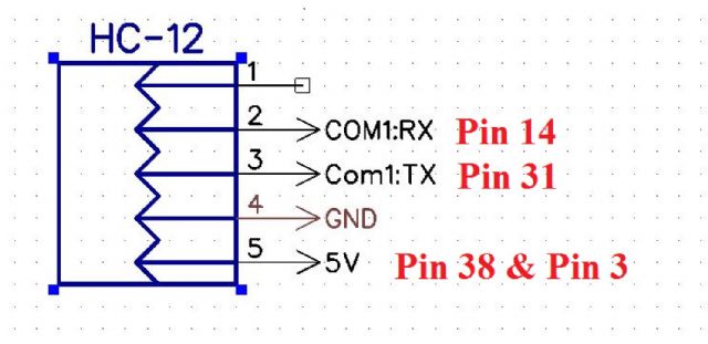 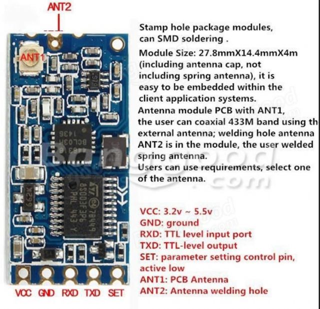 |
||||
palcal Guru Joined: 12/10/2011 Location: AustraliaPosts: 1804 |
Hi Lew, Which micro are you using. Those pins don't make sense Paul "It is better to be ignorant and ask a stupid question than to be plain Stupid and not ask at all" |
||||
| lew247 Guru Joined: 23/12/2015 Location: United KingdomPosts: 1676 |
IT's the E100 board The 80 pin header on it Sorry I should have said the numbers are the pin numbers listed in the table for CON 8 on page 85 in the Silicon Chip article |
||||
| palcal Guru Joined: 12/10/2011 Location: AustraliaPosts: 1804 |
Lew, Just had a look at the article, SC make it a bit hard to understand, they didn't also include Con8 pin nos. I think you have the TX RX pins OK, TX on the SC-12 goes to the 7th pin down on the RH side and RX on the HC-12 goes to 5th pin from the bottom on the left side. The VCC on the HC-12 does not have to go to any pin it just needs to be connected to +5v. or it will work on +3.3v. I bought one of THESE to make life easier, I havn't got it yet so can't comment. Paul edit. Should have mentioned that 5v beside a pin does not mean it is at +5v. It just means it is 5v tolerant. However in the figure on page 85 the second pin from the top on the LH side is +5v so you can use that one and the one above it for GND. edit. just noticed there is a white square beside the top LH pin (GND) that would denote pin 1 on the connector. "It is better to be ignorant and ask a stupid question than to be plain Stupid and not ask at all" |
||||
| lew247 Guru Joined: 23/12/2015 Location: United KingdomPosts: 1676 |
Sorry, my fault when I put the pin numbers that didn't make any sense, they were actually the pin numbers as listed in Diptrace, I should have referred to them the way you did It would have made more sense. Thanks  |
||||
Grogster Admin Group Joined: 31/12/2012 Location: New ZealandPosts: 9066 |
If it makes you feel any better Lew, I have been doing PCB's and working with serial for about 15 years and I still get regularly confused by TXD and RXD. 'RXD and TXD with respect to - which end was it now?'  SparkFun use a nice legend - TXO for TXD out, and RXI for RXD in. That helps a-lot to avoid confusion, but I still end up using TXD and RXD and getting confused, even after all these years working with it! The problem stems from the fact that 'TXD' could me data output OR data input, depending on which way you are looking at it. 'TXD' on one module might mean 'Serial data out to the host', whereas on another module, the exact same 'TXD' label might mean 'Serial data in from the host.' It's been confusing people since they invented asynchronous serial all those years ago! Happily, in MOST cases(not all, but most) the TXD and RXD are with respect to the DEVICE YOU ARE LOOKING AT, so if you have an HC-12 RF module for example, TXD should be data out of the module, and RXD will be data into the module - usually. Smoke makes things work. When the smoke gets out, it stops! |
||||
| lew247 Guru Joined: 23/12/2015 Location: United KingdomPosts: 1676 |
Can someone please confirm which pins on Explore 100 connect to the following SD_CS_PIN on the TFT what pin on the mcu does it connect to? 47? RD pin on the TFT what pin on the mcu does it connect to 6? (the read pin on the tft sd card) I'm using the SD card built into the 7" lcd display with an Explore 100 connected but I can't get the card to read properly |
||||
| Grogster Admin Group Joined: 31/12/2012 Location: New ZealandPosts: 9066 |
Hi. SD_CS: 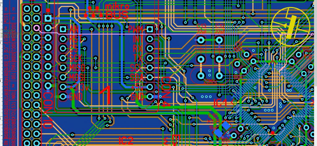 RD: 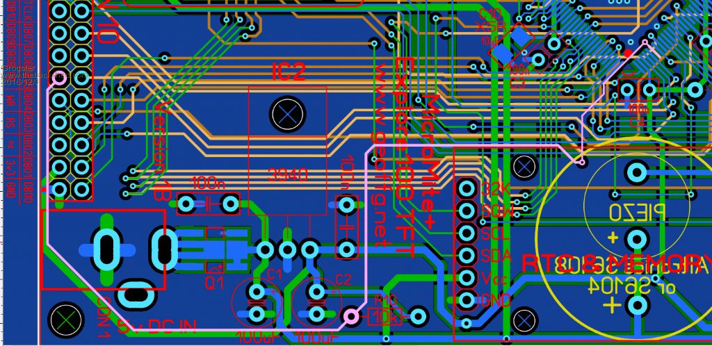 The pink line is the connection test-tool in Sprint Layout, showing where that track goes to. Therefore, SD_CS goes to pin-47 and RD goes to pin-6. Hope that helps. EDIT: Pin-6 is NOT the read pin on the SD card, it is the SSD1963 controller chip read command. If you are trying to use that as SD_DATA_OUT, it will NOT work, and the SD card will refuse to co-operate.  Have a look at this thread about quick E100 setup commands to give you all the correct pin-references for setup of things like the SD card. Smoke makes things work. When the smoke gets out, it stops! |
||||
| lew247 Guru Joined: 23/12/2015 Location: United KingdomPosts: 1676 |
Thanks that helped a lot Next question: How do I stop the SSD1963 display showing console commands? (using the E100 board) It wasn't doing it on the board i made but the E100 it does I tried OPTION LCDPANEL CONSOLE 0ff and I tried OPTION LCDPANEL CONSOLE 0 and I even tried OPTION LCDPANEL CONSOLE 2 but none of them work |
||||
kiiid Guru Joined: 11/05/2013 Location: United KingdomPosts: 671 |
OPTION LCDPANEL NOCONSOLE http://rittle.org -------------- |
||||
| lew247 Guru Joined: 23/12/2015 Location: United KingdomPosts: 1676 |
Thanks kiiid Edit: I did that and the console went off which is great BUT now the lcd is set wrong Its loading the top half of the screen at the bottom and the bottom at the top pics and text commands I did an option list and it came up with this - which I'm pretty certain is correct OPTION LCDPANEL SSD1963_7, LANDSCAPE, 48 OPTION TOUCH 1, 40, 39 OPTION KEYBOARD UK OPTION SDCARD 47 OPTION RTC 67, 66 FIxed it - I had to put all the options in again |
||||
| Phil23 Guru Joined: 27/03/2016 Location: AustraliaPosts: 1664 |
I knocked up this spreadsheet that might be of use. The colours match the ribbon cable I have. 2016-12-03_210821_Micromite_Pinouts.zip Phil |
||||
| Phil23 Guru Joined: 27/03/2016 Location: AustraliaPosts: 1664 |
Tx & Rx? Lol Grog, & they were probably the easy ones. I bet we've both torn out hair over a break-box & devices that are not quite DTE or DCE standards, then attempting to figure out what will work with the other 6 pins. DTR, DSR, RTS, CTS, DCD & RI. Note sure I recall ever needing to use RI. Phil |
||||
OA47 Guru Joined: 11/04/2012 Location: AustraliaPosts: 904 |
IIRC, I once used the RI on a modem to remotely operate a device. Used the RI as not to attract a call cost.  GM |
||||
