
|
|
Forum Index : Microcontroller and PC projects : Reading Thermistors.
| Author | Message | ||||
| Phil23 Guru Joined: 27/03/2016 Location: AustraliaPosts: 1667 |
Before I do too much more "Welding" on the board to control my head pump, can I get some advice on how to connect the thermistors correctly. I've been play with one on a breadboard for a while, so It's basically working, but know there is other considerations. What I Have so far. 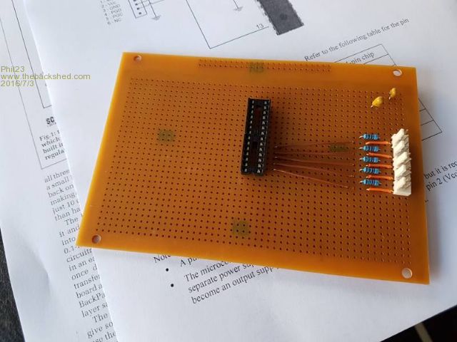
The circuit is this. 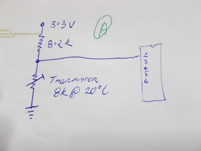
I know I should consider filtering on the inputs, but way past rusty there. Should I do this? 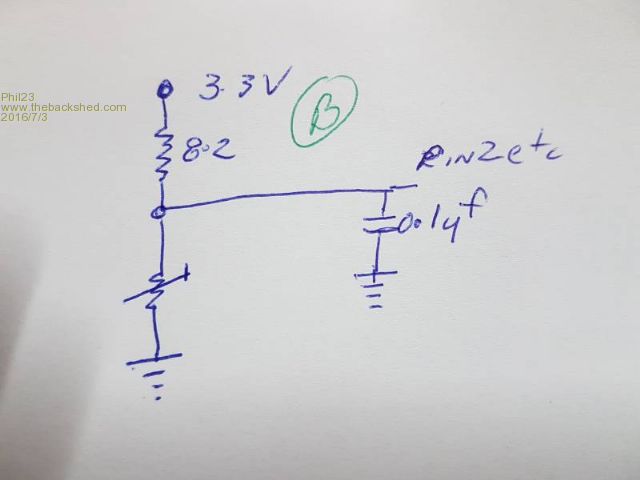
Or this? With what value resistor? 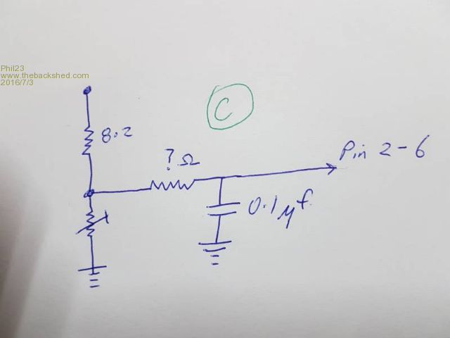
The Heat Pump contains 5 thermistors, 4 of which are installed in a manner such that they are not easily replaced with digital sensors. Their prime purpose is monitoring temperatures to protect the compressor from overloading & the evaporator icing up. So they are buried amongst the 240V components to an extent. Thanks Phil. |
||||
| matherp Guru Joined: 11/12/2012 Location: United KingdomPosts: 11605 |
My approach to this would be in three areas: First, make sure the voltage on AVDD is clean. Use the circuit on the colour Maximite with a resistor and capacitor. Have just a single point of connection between Analog ground and the digital ground. Don't just use the analog ground as part of a single ground plane. Second, it is probably worth having a filter on the inputs 1K + 0.1uF should be OK Finally, and most important is the wiring to the thermistors. I would use two core twisted pair wire with a separate shield. The shield should be grounded at the Micromite end and left open at the thermistor. The two cores then connect to AVDD and Analog ground. |
||||
| Phil23 Guru Joined: 27/03/2016 Location: AustraliaPosts: 1667 |
Thanks Peter, I've already draw heavily on your other post regarding using thermistors. Only thing I don't have a lot of option with is the wiring as the thermistors are already installed. 
All they have is a light twin core attached. Only the ambient one would be easily changed for a DS18B20, but thought I'd leave it in place & add a digital one for reference. They do not need to return precise values, mainly comparisons to protect against failure events. 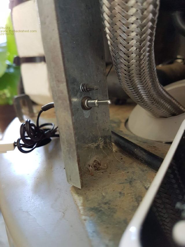
Still having a bit of trouble establishing what the correct co-efficient are for the sensors. I have my own test data & service manual test Temp Vs Resistance values, but they don't quite agree & neither is giving a linear reading. That said, the test bread board is a mess, so could be a contributing factor. Cheers Phil |
||||
crez Senior Member Joined: 24/10/2012 Location: AustraliaPosts: 153 |
Phil, If you have enough filtering on the input then twisted pair is not important. The lowest frequency you need to filter out is 50Hz, so set your filter cut-off around 10Hz and you'll be fine. This corresponds to 1K series resistance with 15 microfarads across the input. With that sort of filtering your reading will still settle at the right value in a few seconds. David |
||||
centrex Guru Joined: 13/11/2011 Location: AustraliaPosts: 320 |
Hi Phil Just a question Why would you not allow the current thermocouples to control the heat pump via its own controller and just turn the power on when heat is required? Cliff |
||||
| Phil23 Guru Joined: 27/03/2016 Location: AustraliaPosts: 1667 |
The Smoke has escaped from the original controller. 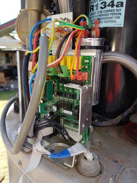
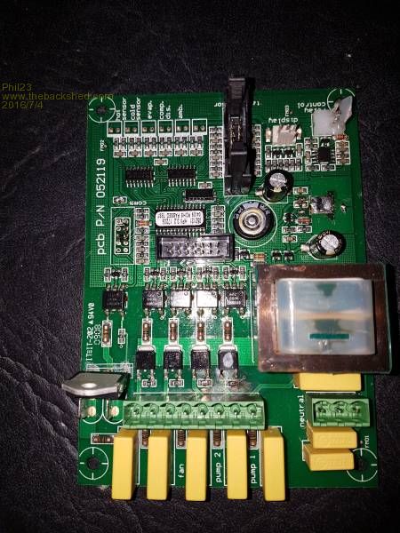
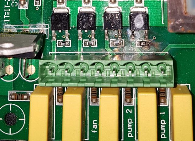
Not even worth considering repairing, as they have a bad reputation, but also, as seen at the bottom of the first picture, it also reads tank sensors connect to the ribbon cables. I believe the circulation pump fails first, if not routinely cleaned, (as if owners will do that), then it's MOSFETS or whatever from there. Can't see why this should happen, as in the event of the pump seizing, the controller should see heat exchanger input/output differences that would indicate a fault. My modified version does away with the storage tank & original circulation pump. Cheers. 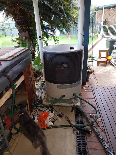
|
||||
| Phil23 Guru Joined: 27/03/2016 Location: AustraliaPosts: 1667 |
Thanks Peter, |
||||
TassyJim Guru Joined: 07/08/2011 Location: AustraliaPosts: 6543 |
|
||||
| Phil23 Guru Joined: 27/03/2016 Location: AustraliaPosts: 1667 |
Ugh, Thanks Jim. Not reading..... Also, realised 10k in series with the thermistor divider circuit would give a 159 Hz cut off. 47k would cut off at about 34Hz. Is that Ok, or am I on the completely wrong track here? I've already added the 0.1�F from the analogue pins to ground. Thanks Phil. |
||||
| matherp Guru Joined: 11/12/2012 Location: United KingdomPosts: 11605 |
Don't go with high value resistors. This increases the input impedance beyond the 10K limit at which the PIC ADC works properly. If you really need a lower filter increase the capacitance instead. |
||||
| Phil23 Guru Joined: 27/03/2016 Location: AustraliaPosts: 1667 |
Thanks Peter, Had no idea about that. Can you recommend a good reference that contains general introductory & helpful information in these areas. Either in print or electronic form, (prefer the latter). Something covering a broad base in basic areas. (Edit:- Not sure if above qualifies as tautology or not). I have little interest in other languages at this stage, mostly interested in circuitry etc. Cheers Phil. |
||||
| matherp Guru Joined: 11/12/2012 Location: United KingdomPosts: 11605 |
Sorry there are no easy guides to this. In fact the recommendation is 5K for the MX170. See AD17 on page 275 of the MX170 device manual The 10K comes from AD15 on the same page However see note 1  |
||||
| The Back Shed's forum code is written, and hosted, in Australia. | © JAQ Software 2026 |
