
|
|
Forum Index : Microcontroller and PC projects : LCD Back Pack MkII?
| Author | Message | ||||
| Phil23 Guru Joined: 27/03/2016 Location: AustraliaPosts: 1667 |
Just wondering if this is a feasible addition to the product line. Thinking of @Grogster, @Bigmik & @Geoffg. Geoff's original is a great form factor & very versatile. Only limitation is I/O pins. Use I˛C for an RTC & decide to implement Com's & you are down to just 7 pins left. So does a 44 Pin version of this form factor make sense? Basically similar to the existing one, just with the additional 14 pins on the bottom edge of the board. Alternatively, I˛C & Com1 pins could be grouped with their own Gnd & Power, much like the existing console connection, making direct connection to those devices very simple. Obviously the bigger backpacks, like the upcoming Explore 100 would blow it out of the water, but they won't have that very compacts form. Think there will always be a demand for that. Cheers Phil. |
||||
CircuitGizmos Guru Joined: 08/09/2011 Location: United StatesPosts: 1427 |
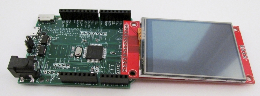
How about the CGMICROBOARD2? 
 Micromites and Maximites! - Beginning Maximite |
||||
| Phil23 Guru Joined: 27/03/2016 Location: AustraliaPosts: 1667 |
Look like just the right thing. Might need to add one to my collection. Thanks. Phil. Edit:- Can't quite tell from the photos, but how is the LCD usually attached. In the first photo is it directly soldered, or on a socket strip. Can see the screw holes are not used. |
||||
| CircuitGizmos Guru Joined: 08/09/2011 Location: United StatesPosts: 1427 |
The CGMICROBOARD2 follows the pin placement and hole positions of the arduino shield. These don't match up with the holes on the LCD. Solder directly or use pin headers - that is up to you. You can use 2.2, 2.4, or 2.8" LCD. Some smaller ones also work. Micromites and Maximites! - Beginning Maximite |
||||
| Phil23 Guru Joined: 27/03/2016 Location: AustraliaPosts: 1667 |
Thanks, Got to the checkout & figured for the freight rate out of US I may as well go back & make it 2. Looking forward to their arrival. Cheers. |
||||
| Phil23 Guru Joined: 27/03/2016 Location: AustraliaPosts: 1667 |
Kicking myself now.... The two I ordered arrived on Friday, and very happy thanks CircuitGizmo. Just wishing I'd thrown a couple of CGMICROKIT MicroMite Kit's in the cart too, given the size of the carton I received. Next question, what sort of shields do others build their projects on? Thinking of something with a reasonable prototyping area & decent type of connections for external devices. At this stage everything is just relying on Dupont connectors, but would rather have something more robust. Have a bit of a collection of 0.1" polarised pin headers & connectors, a shield I could fit them to is roughly what I had in mind. Cheers Phil |
||||
bigmik Guru Joined: 20/06/2011 Location: AustraliaPosts: 2981 |
GDay Phil, It is probably too late but my 28pin based BackPacks have every IO pin accessible for use: Both boards are only 43.5mm x 32.5mm (1.71” x 1.28”) Full details as follows: BackPack170 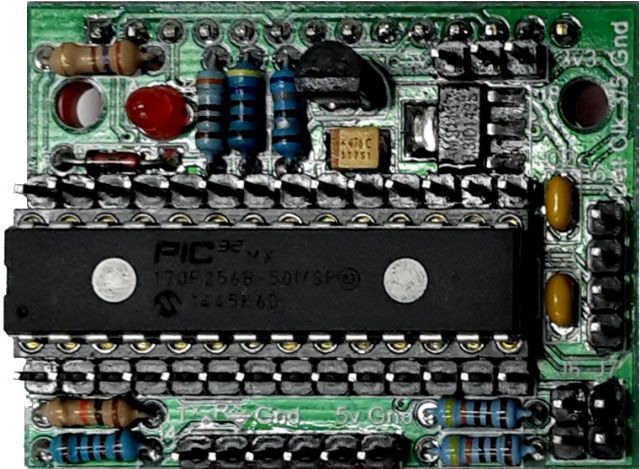
and SMD BackPack170 TOP VIEW 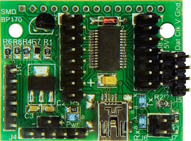
BOTTOM VIEW 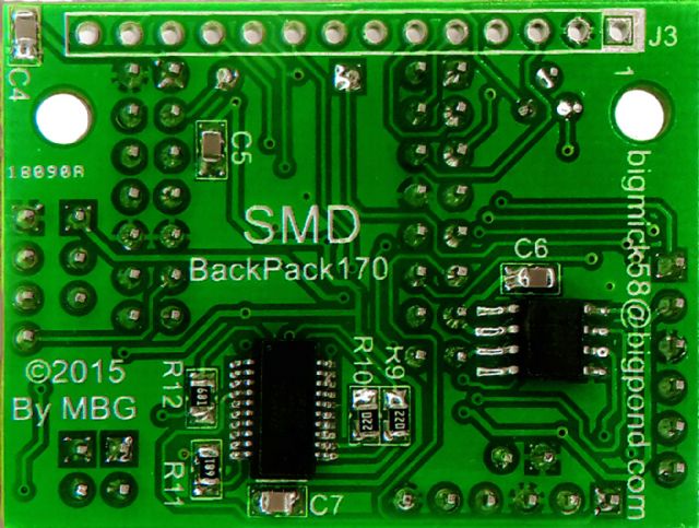
Kind Regards, Mick Mick's uMite Stuff can be found >>> HERE (Kindly hosted by Dontronics) <<< |
||||
centrex Guru Joined: 13/11/2011 Location: AustraliaPosts: 320 |
Or even this one! http://www.thebackshed.com/forum/forum_posts.asp?TID=8805&PN=4 Cliff |
||||
| Phil23 Guru Joined: 27/03/2016 Location: AustraliaPosts: 1667 |
Hi Mick, Have one of your Mup's here, yet to decide where to use it. Thinking the application that requires water resistance when I get to that stage. What I'm looking for at the moment is shields with some strip/proto solder area. Need the alibility to easily disconnect externals to evolve the components. Seems like there's a variety out there, just hard to track down what's most appropriate. Phil. |
||||
| centrex Guru Joined: 13/11/2011 Location: AustraliaPosts: 320 |
Have a look in the JayCar catalogue I can count 3 types one even has terminal blocks. Cliff |
||||
| The Back Shed's forum code is written, and hosted, in Australia. | © JAQ Software 2026 |
