
|
|
Forum Index : Microcontroller and PC projects : LCD Backpack reserved pin error
| Author | Message | ||||
| thirsty Newbie Joined: 22/06/2016 Location: AustraliaPosts: 34 |
OK so I've got the LCD backpack Micromite module and I'm trying to run some 7 Segment LED code shared by mr Mather. I've assigned the pins as per my setup and only using the available pins on the MM board but I'm getting the "Pin 25 is reserved on startup" error. I understand this error happens when a pin is assigned prior to me assigning it but my code is the only code loaded so far as I know. This module came from SC pre loaded with the clock software so I'm assuming the pins I'm having trouble with are pre assigned in that compiled code. Do I have to reflash the MM with a "vanilla" kernel? Can I do something in my code about unassigning the pins I need? Thanks in advance. |
||||
TassyJim Guru Joined: 07/08/2011 Location: AustraliaPosts: 6543 |
A lot of the options are maintained during reboots. Try OPTION LIST That might tell you what pins have been used by the attached devices. Pin 25 is SPI on the 28 pin micromite so might be in use. Jim VK7JH MMedit |
||||
| thirsty Newbie Joined: 22/06/2016 Location: AustraliaPosts: 34 |
Thanks Jim. OPTION LCDPANEL ILI9341, LANDSCAPE, 2, 23, 6 OPTION TOUCH 7, 15 None of those pins are the ones I was using. It looks like the RTC and GPS modules use some pins so I'm guessing they are set in the .hex. I was hoping I could reassign the pins in my code. I don't have my pickit yet so can't reflash the chip either. |
||||
| Phil23 Guru Joined: 27/03/2016 Location: AustraliaPosts: 1667 |
Pin 25 goes to T_Clk on the LCD panel so I'd presume [B/]OPTION TOUCHreserves it. You could try OPTION TOUCH DISABLE to see if it gives pin 25 back, but you will lose the touch capability. You can easily completely erase the clock code with NEW and LIBRARY DELETE. Then load the Clock back later when you want to. Don't need a programmer on hand for those tasks. Cheers Phil. |
||||
| thirsty Newbie Joined: 22/06/2016 Location: AustraliaPosts: 34 |
Thanks Phil. I don't need touch so I did the NEW and then LIBRARY DELETE command and loaded my code back in but same problem. Pin 3 now but that's what it did before, I just kept changing pins until I ran out! I'm trying to drive 4 7 seg LEDs so need 12 pins total. |
||||
| robert.rozee Guru Joined: 31/12/2012 Location: New ZealandPosts: 2541 |
while starting up the micromite, press and hold the "!" key on your terminal (shift-1). the string of "!" characters sent at 38k4 will force the firmware to perform a factory reset and should erase all the options that have been set, along with restoring the terminal baud rate to 38k4 if it has been changed. you can also use an arduino nano (or other 328p based arduino) as a programmer to load new firmware onto the micromite using pic32prog. cheers, rob :-) |
||||
| thirsty Newbie Joined: 22/06/2016 Location: AustraliaPosts: 34 |
Thanks Rob. I'm struggling now with my clone pickit3 to program the 170 on the back back. Using ipe it says it's programmed but nothing is working as it should. Can I use a pro mini with a usb serial interface to use pic32prog? |
||||
| robert.rozee Guru Joined: 31/12/2012 Location: New ZealandPosts: 2541 |
you should be able to - any arduino with a 328p processor running at 16MHz should be ok. in the unlikely event you have trouble uploading the arduino firmware, try the other bootloader speed options (-b1 -b2, -b4). cheers, rob :-) |
||||
| thirsty Newbie Joined: 22/06/2016 Location: AustraliaPosts: 34 |
Thanks Rob. I'll be giving this a go tomorrow once I make up the mini board to take the cables to the Pic. |
||||
| matherp Guru Joined: 11/12/2012 Location: United KingdomPosts: 11606 |
Check the manual - page 17 in the 5.1` version, probably 18 in 5.2 This shows all the pins used by the LCD display. 3, 14, and 25 are the SPI pins so shouldn't be used for anything else except another SPI device. Even in this case you should SPI OPEN and SPI CLOSE each time you need to. If you are using my TM1637 code just use any pins not in the list in the manual as it just bit-bangs the output |
||||
| thirsty Newbie Joined: 22/06/2016 Location: AustraliaPosts: 34 |
Thanks Peter. I solved this problem by reflashing the pic as I don't need the clock. When I say solved though I mean I've swapped one problem for another :) |
||||
| robert.rozee Guru Joined: 31/12/2012 Location: New ZealandPosts: 2541 |
you had success using the arduino mini, or got mplab/pickit3 to work? cheers, rob :-) |
||||
| thirsty Newbie Joined: 22/06/2016 Location: AustraliaPosts: 34 |
I've got the bits Rob to make up the board to try the Arduino Pro Mini tonight. The Pickit3 and Mplab X on my old XP machine doesn't appear to work no. I've programmed the backpack board using the Pickit3 with a very simple program to blink an LED but nothing so I am assuming it hasn't worked. I then programmed the Clock hex file from the SC website which is what my backpack had on it when I bought it but again nothing. I'll post this evening once I try the Arduino method. |
||||
| thirsty Newbie Joined: 22/06/2016 Location: AustraliaPosts: 34 |
OK Arduino Pro Mini with pic32prog working nicely. Now I can program the thing I can get to what I bought it for in the first place! Rob - my version of the mini isn't getting VCC on pins 7,6 and 5. Probably 'cause it's a chinese clone I guess and a little bit different to normal. I'm getting VCC on pins 8 and 9 though. I might jumper those two across along with a third VCC pin I have. |
||||
| robert.rozee Guru Joined: 31/12/2012 Location: New ZealandPosts: 2541 |
that is odd, D2 to D7 are connected to the 328p processor pins PD2 to PD7 on both the nano and pro-mini schematics i have here, so should in theory all behave exactly the same. even chinese clones should follow the same pin wiring between the 328p and the pins around the PCB. you should have something that looks like this: 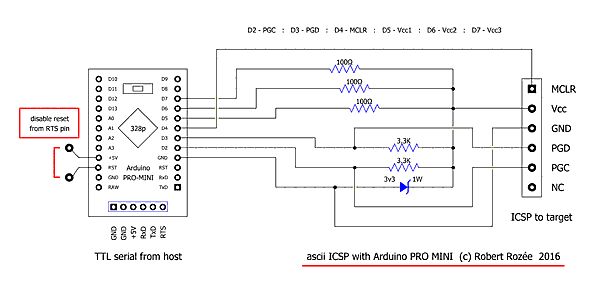
i think i have the above pinouts all correct - this is based upon info from the web, not an actual construction. (oops: i have RTS instead of DTR marked on the schematic) apart from Vcc (3v3) everything else worked ok, and your micromite is up and running the 5.2 version of mmbasic? cheers, rob :-) |
||||
| thirsty Newbie Joined: 22/06/2016 Location: AustraliaPosts: 34 |
Last part of your question - yes, all working nicely thanks to your schematic. I just add power elsewhere to the backpack currently. I'll be having a look at the power side of things tonight. Will advise. |
||||
| thirsty Newbie Joined: 22/06/2016 Location: AustraliaPosts: 34 |
So I stole some power from 3 other pins that had 5v and linked them to the three 100r resistors and am programming firmware in right now. Thanks for your help Rob. Happy for now :) |
||||
| The Back Shed's forum code is written, and hosted, in Australia. | © JAQ Software 2026 |
