Notice. New forum software under development. It's going to miss a few functions and look a bit ugly for a while, but I'm working on it full time now as the old forum was too unstable. Couple days, all good. If you notice any issues, please contact me.
MicroBlocks Guru Joined: 12/05/2012 Location: ThailandPosts: 2209
Posted: 11:14am 12 Jul 2016
Copy link to clipboard
Print this post
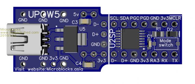
While designing a module that can be use din a breadboard i discovered that there are many varieties.
However i don't know which ones are most common.
What i am interested in to know is the distance between the 'power lines' and the center part. It seems that it is either 100 or 200 mil.
I need this part to fit:
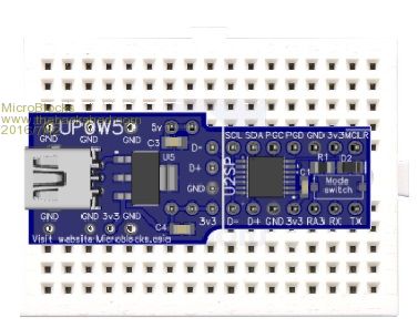
It fits on the little boards i have:
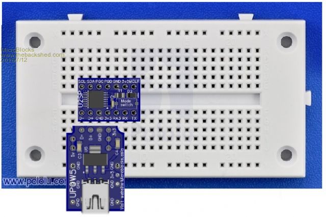
I wonder if the spacing of the GND and 3v3 line up with the powerlines on the larges breadboards.
The design has several pads and the user would be able to choose which one gets a header pin that matches his type of breadboard.
Could you guys see if this design fits the breadboards you use. Don't want to waste time and money to find out later it does not fit.
Edited by MicroBlocks 2016-07-13Microblocks. Build with logic.
Phil23 Guru Joined: 27/03/2016 Location: AustraliaPosts: 1667
Posted: 04:36pm 12 Jul 2016
Copy link to clipboard
Print this post
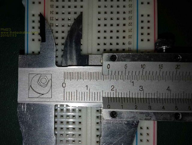
Does this help?
I didn't check if it's something like 1.5x pin pitch.
MicroBlocks Guru Joined: 12/05/2012 Location: ThailandPosts: 2209
Posted: 08:24pm 12 Jul 2016
Copy link to clipboard
Print this post
Thanks Phil, that helps.
Yours is actually one of the more difficult ones to add. As the holes from the powerlines are not on the same grid as the rest.
I'll see if i can move some pads around to also support this breadboard.
Microblocks. Build with logic.
paceman Guru Joined: 07/10/2011 Location: AustraliaPosts: 1329
Posted: 03:12am 13 Jul 2016
Copy link to clipboard
Print this post
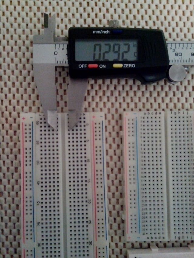
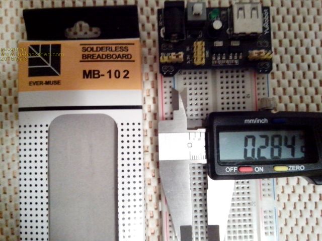
Hi Jean, I've tried to standardise on the ones below with the red and blue voltage rails. The last ones I received came from the pack shown in the second photo but I also have one double that size on an aluminium backplate which is marked "E.I.C. E-CALL" and below "EIC-104". They have a 0.1" grid with 0.3" across the centres and 0.3" from the grid side holes to the closest rail.
These fit those little dual supplies which seem to be everywhere. The voltage rails on these are separate and clipped together before the sticky yellow back is applied. They often don't quite line the holes in the rails up properly with the main grid though which can be a bit annoying but the two sets of rails either side do seem to always line up, so those little dual supplies always line up OK. On some of the small size ones I received the red and blue rails were reversed from one side to the other so you have to watch that.
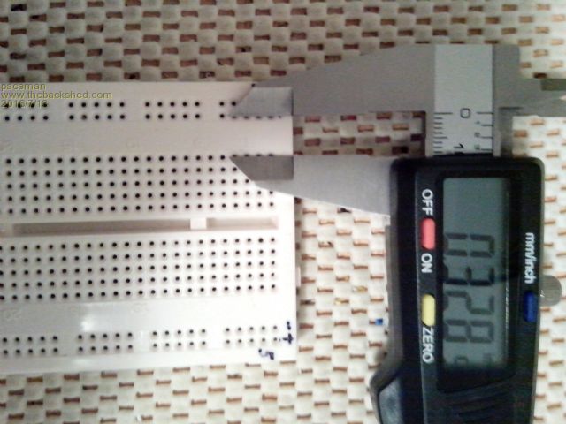
I also have some of the (unmarked) ones you showed above (last photo) which I didn't realise would be different. They have the same 0.3" spacing in the middle but have a wider spacing to the rails, about 0.33" (see the photo). This breaks the overall 0.1" grid so that dual supply doesn't fit! They're also a single moulding, not three like the others (two rail sets plus main grid) which does at least have the advantage of lining up the rails and grid but I've given up using them because of the supply not fitting.
Greg (BTW, micrometer is reading in inches)
MicroBlocks Guru Joined: 12/05/2012 Location: ThailandPosts: 2209
Posted: 05:08am 13 Jul 2016
Copy link to clipboard
Print this post
Thanks!
The more i look into breadboards the more weird ones i find.
I think i stick with the ones that keep the 0.1" grid. That seems the most logical.
Microblocks. Build with logic.
WhiteWizzard Guru Joined: 05/04/2013 Location: United KingdomPosts: 2991
Posted: 05:39am 13 Jul 2016
Copy link to clipboard
Print this post
@MicroBlocks
Personally I would keep all your pins confined on a Horizontal row (or rows), and let the 'BreadBoard User' use jumpers to connect from your module's power output pins to their breadboard power rails. This way you keep your unit small(er), and all breadboards will be covered no matter what spacing their Power rails.
WW
MicroBlocks Guru Joined: 12/05/2012 Location: ThailandPosts: 2209
Posted: 06:30am 13 Jul 2016
Copy link to clipboard
Print this post
All pins are available when plugged in vertical or horizontally. The extra pads are for adding more rigidity when using the USB connector.
I thought if i can line those up with the power rails when used vertically then it would be a bonus.
Edited by MicroBlocks 2016-07-14Microblocks. Build with logic.