
|
|
Forum Index : Microcontroller and PC projects : Guage Update...
| Page 1 of 2 |
|||||
| Author | Message | ||||
| Zonker Guru Joined: 18/08/2012 Location: United StatesPosts: 772 |
It's been awhile since I posted an update.. I took a side track and did Lou's PEMF Coil Driver PCB which should be on it's way from Iteed soon... So, back to Gauge code... 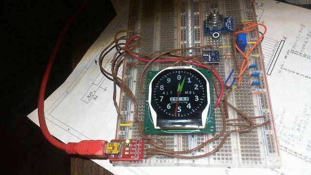
I changed the user interface from push buttons to an encoder type control with push "select" button, which works like the old school gauge. Also included 2 setup screens to change either the QNH scaled in in/mg or ALT in ten's of feet. I will be building a battery powered "test" unit and have my Bro Dave take it up for a test flight to see if it seems to work ok... I big tip of the hat to Peter for writing the BMP180 and updated R61505V driver which supports the RD pin, that makes all this work..! 
Since the gauge interface board also contains an Rs-485 transceiver, I am now thinking of transmitting the ALT information to another gauge display and create a "rate of climb" type unit... Should be doable... Project code attached if interested... 2016-07-23_053150_ALT_Versa_Gauge_Program_v2_encoder_with_setup.zip Stash the driver and fonts in the library 2016-07-23_053341_UPDATED_Versa_Gauge_R61505V_Driver_&_Fonts.zip Thanks TBS..!! I love toys..! |
||||
| Bill7300 Senior Member Joined: 05/08/2014 Location: AustraliaPosts: 159 |
Looking really good. QNH entry in millibars ( a.k.a hectapacals ) would make it universal. Shame that your Aliexpress supplier no longer stocks the LCD, only a slightly smaller 2.0" version of lesser resolution. Bill Bill |
||||
lew247 Guru Joined: 23/12/2015 Location: United KingdomPosts: 1709 |
Beautiful work, I love the thin red needle Is the background - the Black with the numbers a background picture or drawn by the Micromite? |
||||
| robert.rozee Guru Joined: 31/12/2012 Location: New ZealandPosts: 2541 |
a really neat piece of kit you've designed 
note: the BMP180 is light sensitive, i found i needed to place a black light shield around the module otherwise altitude would vary by 50 metres or more if exposed to sunlight. this just by light entering that tiny little air hole in the top of the metal can. cheers, rob :-) |
||||
| Zonker Guru Joined: 18/08/2012 Location: United StatesPosts: 772 |
Vertical Speed Indicator add on... 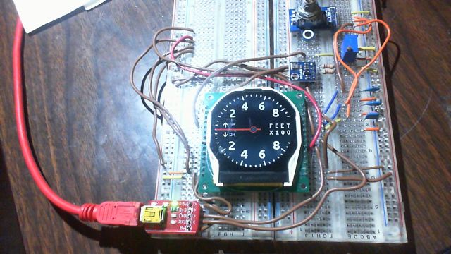
I am still trying to get this worked out, but got the background screen worked up... Instead of using 2 gauge displays, I think I can just hit the button and switch between them... I think I will need some help from Peter Mather on how to properly control the needle objects buffer to switch from showing 3 needles to just 1 on the vario display... I tried just clearing the "buff()" array but can't seem to clear the other 2 needles once they exist.. 
@lew247 - The needle designs are the same ones Peter used in the clock demo that he wrote and posted.. I haven't created new ones yet, and maybe don't need to as these seem to look OK as is... The gauge backgrounds are just drawn using the tick mark SUB, (again a modification of Peters code) and the fonts loaded into the library flash area... (see code example above) @Bill7300 - The original code from Peter was displayed in millibars (hectapacals) and I just changed it to in/mg... I think I could include a setup screen to allow the end user to change it to either type if wanted... Also, the hand held prototype test unit went "flying" yesterday thanks to Bro Dave and a CFI he is training with.. One confusing thing is that entering the ATIS info from the airports seems to be just the airports "local" air pressure and is not "adjusted" the sea level pressure (as in QNH) I am still trying to get the correct answers to this question... (don't know yet)... Anyway, still workin on it... I did order the 10 new displays from the WayEngineer site and they seem to be on the way... Still lot's of work to do... But with some help from Peter, I think this Gauge should be possible... Next, I want to take a crack at doing an airspeed gauge... still looking at proper sensors... the Servflow website has a few that use the SPI interface that look good, But I am in enough trouble just getting this one worked out for now... I don't get enough time to spend "in big chunks", so progress is slow... (yikes.. 10 hour days at work)... I still have some vacation days left so when the Rev-B PCB's get here I will get some built up and start on getting the encoder knob designed onto the interface board... A big tip of the hat goes to Peter Mather for all the code he has created to make this thing work..!!!
|
||||
Grogster Admin Group Joined: 31/12/2012 Location: New ZealandPosts: 9985 |
I fully expect TCAS and ILS by the end of next week..... 
(for those not into aviation in any way, this is short for Traffic Collision Avoidance System and Instrument Landing System - both very well established cockpit systems in any modern aircraft of any size. little single-engined personal aircraft don't have these so I understand, I think they just use VFR - Visual Flight Rules.) Beautiful looking displays - I might have to start looking at those circular LCD's myself at this rate - all the hard work has been done by you and Peter(Mather). Smoke makes things work. When the smoke gets out, it stops! |
||||
| paceman Guru Joined: 07/10/2011 Location: AustraliaPosts: 1329 |
Looks great Zonker. If you're doing an Airspeed indicator then you'll have pitot's all sussed out so how about an Angle of Attack (Stall) meter too 
Greg |
||||
| Zonker Guru Joined: 18/08/2012 Location: United StatesPosts: 772 |
Yep.. There has been talk of it already... Too many toys, not enough time..! 
EDIT: - I do remember a buddy, Dick Cole who had a Klob high wing Ultralight that had a simple AOA readout that consisted of a sensor that was a simple "wind vain" kinda thing with a pivot point to a simple 3 wire POT on the pivot shaft feeding back to a simple "BAR" type segment voltmeter arrangement... It seemed simple, and Dick said it worked like a champ... So maybe it wont be to hard after all.. 
|
||||
| paceman Guru Joined: 07/10/2011 Location: AustraliaPosts: 1329 |
Yes my brother-in-law built a KitFox 2-seater and he mentioned the "vane" type as a simpler (cheaper) possibility. I was thinking along the lines of this link Sonex64 but it starts to cost when you look at the Honeywell sensor price (US$50, A$70...gulp), and then you need two of them for proper AoA not to mention the pitot's! - the circuit he shows is dead cheap mind you
Greg |
||||
| Zonker Guru Joined: 18/08/2012 Location: United StatesPosts: 772 |
Awesome Greg..!! An excellent source of reference information about the needed "front end" of the design needed for the gauge readout... Even though the cost of doing the design with the pressure sensors is higher, it might be the better way to go... (not sure yet) If we could find more info on the "weather vain" type sensor, we could better determine which way to go... Either method requires the pilot to properly "calibrate" the sensor setup to match his/her aircraft, and is the "tricky" part of the final installation... Proper instructions would have to be included in the final "package" of parts to the end user of this type of gauge... I will have to do more thinking about this, as I sure as hell don't want to be responsible for anyone getting hurt or trashing there aircraft because the installation was not done correctly..!! 
Anyway, Thanks much for the info about this..! I will take a look at some pressure sensors and post the finds here.. I think the ones that have SPI port outputs would be best, as we then don't need any "analog front end" circuit.. Head scratching time needed... |
||||
| Paul_L Guru Joined: 03/03/2016 Location: United StatesPosts: 769 |
Boeing aircraft types use physical angle of attack (stall) sensors like these, http://www.ameteksensors.com/Products/Angle-of-Attack-Sensors.aspx which don't display anything in the cockpit, they just physically shake the control yoke (stick). They also use an IVSI or Instantaneous Vertical Speed Indicator instead of just a VSI. You really want to get the gear up very quickly after liftoff to reduce drag. If you waited for an aneroid VSI indicator to respond to air pressure changes it would be too slow. The IVSI indicator includes an accelerometer in addition to an aneroid diaphragm which reacts more quickly to initial liftoff and doesn't sense a false climb resulting from high speed air turbulence while still on the runway. |
||||
| Zonker Guru Joined: 18/08/2012 Location: United StatesPosts: 772 |
Airspeed sensor... I found this on the ServoFlow site.... Not sure which range yet, but, it uses the I2C bus, and is calibrated... 2016-08-15_025600_sm9541.zip I had to zip it or it wouldn't fit in the 500k limit... I think 0 to 2, maybe 3 PSI is the range needed for an airspeed sensor (I think)... This looks kinda expensive... |
||||
| matherp Guru Joined: 11/12/2012 Location: United KingdomPosts: 11608 |
I've used these in a past life |
||||
| paceman Guru Joined: 07/10/2011 Location: AustraliaPosts: 1329 |
That's too high a range - unless you've got a Spitfire . The table I have says ramspeed at 100 Knots is 0.236 psi, i.e. 6.54" H2O, so Peter's option (NXP MPXV5004DP max. pressure 3.92KPa, 15.8" H2O) is much closer and a hell of a lot cheaper (US$12.30 at DigiKey, 7.60 UK pounds at Element 14).
The Honeywell ASDX001D44R used in that earlier Sonex64 link tops out at 27.7" H20 so as he said, that's really a bit high (depending what you're flying). The more sensitive option he suggested to use is the ASDXL10D44D (DigiKey P/No. 480-1918-ND) which tops at 9.96" H20 (which would be a good range) but they're very expensive. Peter's option should be good for mortal flyers and he says it works so I'd say that's the way to go. There might be a slightly lower range one below that now that would be better still but I haven't checked that. Greg |
||||
| Zonker Guru Joined: 18/08/2012 Location: United StatesPosts: 772 |
Thanks Peter and Greg..!! I am kinda new at trying to select sensors and could not seem to find a "cheat sheet" that does all the conversion between in of H2O, PSI and k/pa...
Can I see a copy of your conversion table you use Greg..? So Peter, I would then take the analog output into the MM A/D pin without any voltage scaling. Glancing at the data sheet seems to say 1 volt per kPa and spans to 3.92 volts at it's "top of scale"... So, since it is higher than 3.3 volts, what would be a good way of protecting the MM pin..? Also, I read in the data sheet their output at 3 volts is 3 kPa or 306 mm H2O... (here we go again)...
Anyway, I am having trouble wrapping my little (8-bit) brain around all this, and need a little (a lot) of help getting this voltage converted into speed to show on the gauge face... Thanks MUCH Gent's for your help on this (for me hard) stuff..!!
|
||||
| thirsty Newbie Joined: 22/06/2016 Location: AustraliaPosts: 34 |
I was looking at how to calibrate the ASI in my own plane recently and stumbled across this page This page has the table mentioned and other information that might be useful. |
||||
| Bill7300 Senior Member Joined: 05/08/2014 Location: AustraliaPosts: 159 |
I have been away from home the past few days, so I'm now catching up on this thread. I have been following the Sonex64 design for the past few years but haven't yet found a reasonably priced source for the pressure sensors needed for his "true AOA" version. If you are interested in the vane type, one employing a Hall Effect transducer, you might like to take a look at vane type He again has his kit available, after an absence of some years. I found the design just as he had sold out of kits a couple of years ago. I did manage to get some components from him but need to complete the vane itself once I make the time. Frankly, at the price he is charging, I would simply buy the complete kit if I were starting out now. Bill Bill |
||||
| Zonker Guru Joined: 18/08/2012 Location: United StatesPosts: 772 |
Wow.. Ok... I will need a little "head scratchin time" on this, but I think I can see a plan here... So, lets start off by getting the parts for sensor and CAL setup... Then, get things connected to a MM gauge engine PCB to see how the scale works out.... Big tip of the hat to you fine Gent's for pointing me down the right road... I will post back when I can get this stuff scraped together...
|
||||
| thirsty Newbie Joined: 22/06/2016 Location: AustraliaPosts: 34 |
A bit of light reading for you! |
||||
| paceman Guru Joined: 07/10/2011 Location: AustraliaPosts: 1329 |
It's in a .jpg file unfortunately but here 'tis. 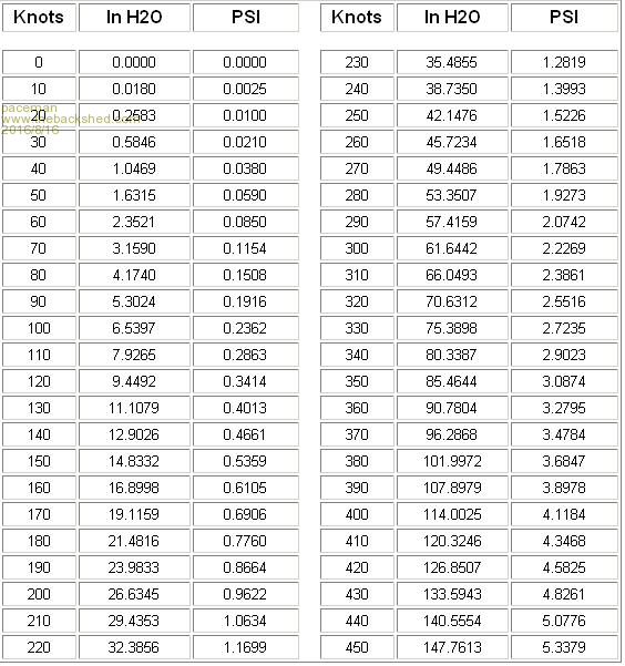
Bill's link to the BarkerAircraft kit using the vane and Hall sensor looks a very good option though too. Pretty good at US$60 over your way. Mounting it his way on the ASI pitot would make things easier too. I'm not sure quite where you'd need to mount the pitot for the differential pressure type but it would certainly be a more complicated and expensive option. His circuit and method of mounting the LED's in a 2.25" gauge would match nicely too if your current instruments are 2.25 inchers - which my brother-in-law's are, but the analogue outputs are still there for the MMBasic and round LCD display approach. BTW, you can get pretty much any conversion quickly by just Googling "CONVERT blah to blah" in you browser - the factors are usually given too. Greg |
||||
| Page 1 of 2 |
|||||
| The Back Shed's forum code is written, and hosted, in Australia. | © JAQ Software 2026 |
