
|
|
Forum Index : Microcontroller and PC projects : MM+: E100 Prototyping Board...
| Page 1 of 4 |
|||||
| Author | Message | ||||
Grogster Admin Group Joined: 31/12/2012 Location: New ZealandPosts: 9931 |
Hi folks. 
Phil23 had asked me about a prototyping board for the MM+ E100, so here it is: 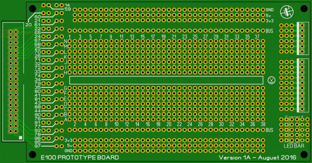
This idea was all Phil23's not mine, but he is right - it may appeal to others wanting to do prototype designs with the E100 unit. Board size is 138mm x 77mm not including the area for the 2x20 connector.(150 x 77 including that bit) I am going to do a version of this for the E64 too, but that will be published in a future thread - not too long away, a week or so probably. This one can plug DIRECTLY into the E100's GPIO port(CON8) via a 2x20 female header mounted on the bottom of the board, or you can also use the mounting holes and a short IDC cable(and fit a standard 2x20 box-header on the top side of the board). It's pretty self-explanatory in arrangement, but the header sockets on the right side of the board were at Phil's request, and also there is a 5-segment LED bar-graph on the lower right of the board, for any LED's you may wish to add. You could substitute standard rectangular LED's here, if you wanted different colours, and there is provision for that under the bar-graph footprint via an extra set of holes. The gap in the middle of the prototyping area is the standard 7.62mm of all DIL IC's etc. The pins on the GPIO port are all broken out to 1x2 pads, but not connected to any of the columns in the prototyping area. The idea behind that is so that you can configure the prototype area however you want. Routing the pins out directly to the columns on the prototype area would invariably not suit the pinout of some devices under test. Leaving this bit up to you, means you can setup the board however you want to suit anything in any pin-order. Configuration of this aspect of the design is easy-peasy: I suggest using self-fluxing enamelled copper wire on the bottom side of the board. This enamelled wire is the stuff that you just heat up with the iron, and the enamel melts, apply some solder to tin the end, and you are away. You don't even have to do that - just cut the lengths you want, thread them to where-ever, then apply heat, wait for the enamel to melt, and apply solder and you will tin and solder the wire to the pad all in one operation. The PCB pad may not like that too much though, as you normally have to apply the heat to the enamel for a reasonable time before it melts, but whatever you are happy with.... It should be noted that some PCB houses will not let you make a board with a matrix of holes like this, because it represents excessive wear on their drillbits.... I have approval from a PCB house who will make these for me, and these boards have already been ordered, and I will be offering them on the website in due course. The price is expected to be about US$15 per board, but I have yet to confirm that - watch this space. Smoke makes things work. When the smoke gets out, it stops! |
||||
| Phil23 Guru Joined: 27/03/2016 Location: AustraliaPosts: 1667 |
Thanks Grog, This missing link has plagued me for a while. While I have 4 MM's running now, they are still on solderless breadboards. Component counts are small, just a handful of resistors, a few caps, & maybe a couple of driver transistors to come. Inputs & outputs are plenty, & the final solution of what to build it on was always the missing link. I've got strip board & dozens of different PCB's in various shapes & sizes. All with limitations, & all in need of lots of connections back to the Micromite. Designs made on the Solderless should be easily replicated on this & decent external connectors put to use. I know there are plenty on here that can design & order their own custom boards, but for many of us it's not an option. Simple as it may be to begin down that road, time is something that is just not available for another learning curve. Great work Grog, & look forward to others comments. Cheers Phil. |
||||
| MicroBlocks Guru Joined: 12/05/2012 Location: ThailandPosts: 2209 |
One of our members (Kiiid) has done a successful kickstarter for a prototyping board that could fill the need. It would also be good to use for a final product. Take a look: https://www.kickstarter.com/projects/knivd/routaboard-the-prototyping-board Microblocks. Build with logic. |
||||
| Phil23 Guru Joined: 27/03/2016 Location: AustraliaPosts: 1667 |
Pretty sure this can be used for the final product in may cases, & the great thing is that it presents all the MM's pins right there on the board ready to go. Spent a bit of time looking at what is available for Arduino & RPi, & felt that this was something missing in the MM world. Bigmik is doing looking at something for the smaller MM's too, & I know I can put his version to use. Who knows, might end up seeing some new projects built on these, that other new uses might like to replicate. Cheers Phil. |
||||
f1fco Senior Member Joined: 18/03/2012 Location: FrancePosts: 155 |
Hi Grogster, what news about the SD card board (to plug on CON10) whe speak about here : http://www.thebackshed.com/forum/forum_posts.asp?TID=8796&PN=4&TPN=3 I am also interested by this proto board thanks Pierre. 73s de F1FCO |
||||
| Zonker Guru Joined: 18/08/2012 Location: United StatesPosts: 772 |
Sweet..!! Sign me up Grogs... This is the perfect add-on to the E100 I got coming in soon..!!  |
||||
| LouisG Senior Member Joined: 19/03/2016 Location: AustraliaPosts: 130 |
Very nice, Grogster! Would those 1x2 pads by any chance be spaced 0.156"? Would it be possible to stagger the printed pin numbers for better readability? e.g. 60 21 61 22 66 24 ...etc. Louis |
||||
| LouisG Senior Member Joined: 19/03/2016 Location: AustraliaPosts: 130 |
Should read ...60 21 ...61 22 ...66 24 |
||||
| Grogster Admin Group Joined: 31/12/2012 Location: New ZealandPosts: 9931 |
Thanks for the reminder - I had forgotten about that.... I will design one to use a standard SD card soon, and put that up - thanks also for the link to the other thread, as I forgot posting that too!!! 
Too many things to do, not enough time, but this board is simple enough, so give me a week or so, and I will have something I can offer. @ LouisG - YES, 1x2 pads are standard 2.54mm or 0.1" spacing, BUT they are not on the same grid as the prototyping area as I am sure you can see. They are standard 0.1" spacing though. I did not get around to ordering the boards last night, so I can still make the change to the pinout text you asked for - that is a sensible idea. Smoke makes things work. When the smoke gets out, it stops! |
||||
| MicroBlocks Guru Joined: 12/05/2012 Location: ThailandPosts: 2209 |
@Grogster, Would adding two power lanes in the center be possible. There is room available. A 3v3 and GND lane would allow for very short wires to connect power to a module/chip. As most of them are 3v3 the 3v3 and gnd combination seems nice. You could also then very easy add little decoupling capacitors. I indicated the area with a yellow border: 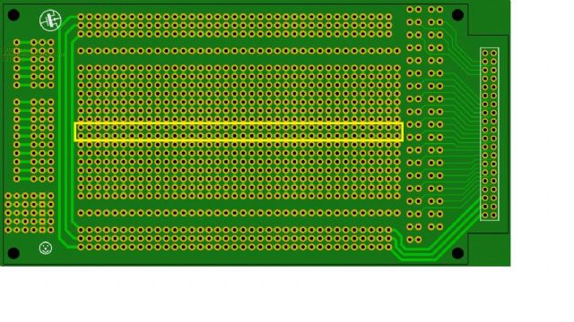
Microblocks. Build with logic. |
||||
| Grogster Admin Group Joined: 31/12/2012 Location: New ZealandPosts: 9931 |
OK, yeah, I can do that - I figured the gap was a good thing, but I guess the silkscreen shows where DIL chips need to be. With the greatest respect to all here on the forums, this is the last change I will make to this board, otherwise the design-by-committee thing prevents the boards from ever being made. 
Don't get me wrong - your idea and LouisG's idea are fine(in fact most ideas are), but you have to call it at some point or you are forever changing the design to try to accomodate everyone, and the board sits in limbo while various ideas are in debate.
...I've already had a PM about perhaps adding a flux-capacitor - I kid you not, although I know the PM was in jest.... 
[Quote=A Private Message]Do you think you could add dual "Flux Capacitors"?, and make simultaneous time travel to single destinations at different dates an additional feature. I'd suggest you based that on a Lotus Esprite, rather than the previously used DeLorean, as It's known from James Bond Movies that the Lotus's can go under water... Also the 88mph required for the Delorean to slip thru time may be worthy of revision & lowering to possibly 40km/h given the prevalence of speed cameras these days. That was hilarious - my thanks to the author of that PM, who shall remain nameless for privacy reasons, naturally. Smoke makes things work. When the smoke gets out, it stops! |
||||
Lou Senior Member Joined: 01/02/2014 Location: United StatesPosts: 229 |
OK, the PM was great. Now somebody fess up and take the credit !! And the underwater Lotus - was that 'The Spy who loved me' ?? I think it was. Lou Microcontrollers - the other white meat |
||||
| Grogster Admin Group Joined: 31/12/2012 Location: New ZealandPosts: 9931 |
Being something of a big fan of the BTTF trilogy, this PM I particularly enjoyed.
If the author wishes to say who it was, that is up to them - I will confirm IF they lay claim to it, but if not, you will just have to live with the mystery! Smoke makes things work. When the smoke gets out, it stops! |
||||
| Grogster Admin Group Joined: 31/12/2012 Location: New ZealandPosts: 9931 |
UPDATE: This is what has now been ordered. 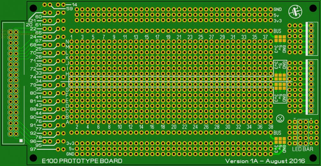
This adds the two extra "Bus-bars" that MicroBlocks wanted, and also staggers the pin numbering to make them easier to find by running your eyes up or down the numbers. I have also added four groups of solder-blob pads around the two new rows in the center, and also around the pre-existing buses at top and bottom, so that you can solder-blob to make these bars whatever you like - ground, 3v3 or 5v - you choose by setting the solder-blobs. Assuming you don't change this TOO often or use too much heat when you do, the pads should not de-laminate from the board, but this is more of a "Set it and forget it" idea then one you would change often. I think this makes it very usable - I might even use it myself! Smoke makes things work. When the smoke gets out, it stops! |
||||
| Grogster Admin Group Joined: 31/12/2012 Location: New ZealandPosts: 9931 |
UPDATE: These boards will sell for US$10 each(+ postage) NOT US$15 as previously stated. The price for these boards came out rather good considering all the extra drilling for a board like this, so I am able to offer them cheaper then I first thought.
I have only ordered 25 boards, and I will be holding back five for myself, so that means there are twenty available as a first order - I can certainly get more if there is any interest at all.... Postage will be US$2.50 for standard airmail to anywhere on the planet, as these boards are small enough to fit in a DLE envelope. So, in other words, US$12.50 per board INCLUDING airmail postage to anywhere on the planet. I will also include some self-fluxing enamelled copper wire for doing the links. This will go up on the website soon. Smoke makes things work. When the smoke gets out, it stops! |
||||
| LouisG Senior Member Joined: 19/03/2016 Location: AustraliaPosts: 130 |
Please reserve one board for me. ....Louis |
||||
| Zonker Guru Joined: 18/08/2012 Location: United StatesPosts: 772 |
Sweet..! Reserve 2 for me also... I will check the website for updates and order them there or can pal-pal you the funds directly... Which ever is best for you.. Thanks G..! Looks awesome... |
||||
| MicroBlocks Guru Joined: 12/05/2012 Location: ThailandPosts: 2209 |
Looking good! I have to hold out a bit as what is left of the funds is reserved. Not going to play with a 100 pinner soon, so i might get back to this in the future. Microblocks. Build with logic. |
||||
| Phil23 Guru Joined: 27/03/2016 Location: AustraliaPosts: 1667 |
Who? Me? |
||||
| Grogster Admin Group Joined: 31/12/2012 Location: New ZealandPosts: 9931 |
Confirmed. Smoke makes things work. When the smoke gets out, it stops! |
||||
| Page 1 of 4 |
|||||
| The Back Shed's forum code is written, and hosted, in Australia. | © JAQ Software 2026 |
