Notice. New forum software under development. It's going to miss a few functions and look a bit ugly for a while, but I'm working on it full time now as the old forum was too unstable. Couple days, all good. If you notice any issues, please contact me.
dhester Newbie Joined: 17/07/2016 Location: United KingdomPosts: 11
Posted: 09:50am 21 Aug 2016
Copy link to clipboard
Print this post
Just got around to constructing my explore100, I got the one with presoldered smd parts.
I powered the board via a wall plug into J1 and bridged the pins to provide power from the usb, and usedbJ6 fro the serial into teraterm on my pc.
I can get the red and yellow leds to blink, got rtc working but I am having problems with the lcd.
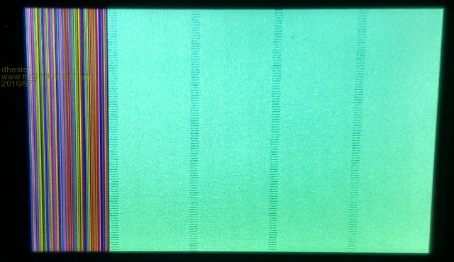
I have tried a 5" and 4" ssd1963 I use option lcdpanel, ssd1963_5, L, 48 and get the following results
Also when use a min usb cable from my pc into J1 nothing happens.
Can anyone suggest where to start trouble shooting
palcal Guru Joined: 12/10/2011 Location: AustraliaPosts: 2039
Posted: 10:57am 21 Aug 2016
Copy link to clipboard
Print this post
Check for bridges on the PCB, Mikeb had a problem.
Paul"It is better to be ignorant and ask a stupid question than to be plain Stupid and not ask at all"
Grogster Admin Group Joined: 31/12/2012 Location: New ZealandPosts: 9985
Posted: 02:50pm 21 Aug 2016
Copy link to clipboard
Print this post
Odd....
I assume that this LCD works fine if you hook it up to something else, yes?
IE: We know the LCD is OK and it is not a crook LCD, yes?
Assuming that is the case for now, disable the LCD(OPTION LCDPANEL DISABLE at the command prompt), then put an LED + 1k resistor between each of the LCD data-bus and control lines and ground, and run a code to cycle through the LED's one by one. Only ONE LED should ever light at any one time, and only when the code steps to it. If you step to one pin, and more then one LED lights, we have a short somewhere.
I triple-checked all these boards under the scope and monocle, and was damn sure I did not have any bridges, but it is always possible I missed one or two in the dozens of boards I have done so far.
J1 is a jumper. Install a jumper-shunt on this, and then you can use the USB for a power supply. You only need to install a shunt on J1 if you want to use USB power, but if you DON'T put a jumper on J1, the USB 5v is not passed to the system, so it won't power up.
DO NOT use USB power and external power via the DC socket at the same time.Smoke makes things work. When the smoke gets out, it stops!
LouisG Senior Member Joined: 19/03/2016 Location: AustraliaPosts: 130
Posted: 08:11pm 21 Aug 2016
Copy link to clipboard
Print this post
This type of problem has reminded me to first check my E100 board when it arrives, before starting assembly. Will go round the 100 pins checking for shorts between adjacent pins. Should only take a few minutes.
Actually, this would be good practice after receiving any type of PCB following manufacture.
@Grogster
Since the MX470 chip is already soldered to the board, which Ohms range on the multimeter would you suggest for checking for shorts, considering that the chip contains 1.8V logic circuitry?
mikeb Senior Member Joined: 10/04/2016 Location: AustraliaPosts: 180
Posted: 08:25pm 21 Aug 2016
Copy link to clipboard
Print this post
@LouisG
Now you're going to get Grogs paranoid . Look at his post first and do what he recommended. It is an excellent 'first off' method. You could probably do the same with ALL control signals to the LCD panel. Refer to the schematic in his 'Constructor' Pack. Probably worthwhile testing the LCD panel on something else if you have available. Or use another LCD panel. If you got LED's to blink, and the RTC to work, then your serial ports are obviously OK. Must admit I'm a bit 'taken aback' as to how you powered the board. There are 10 kinds of people in the world. Those that understand binary and those that don't.
Grogster Admin Group Joined: 31/12/2012 Location: New ZealandPosts: 9985
Posted: 09:16pm 21 Aug 2016
Copy link to clipboard
Print this post
Provided the board is NOT powered, you should be able to use the 10k or 20k range on your multimeter. Low-ohms range can allow more current to flow in the continuity test then we really want floating around the I/O pins, so don't use those ranges. If in any doubt, put a 10k resistor in series with one of your meter probes, then do the tests. Tests for shorts will then read as 10k(the one in your meter lead), but that 10k will ensure that no serious current is flowing via the meter's probes. If you DO elect to do this on the board before you assemble it, ensure that correct anti-static precautions are being observed, as with nothing soldered to the board, it won't have any natural circuit impedance to protect the I/O pins. Once assembled, the rest of the board circuitry protects the IC against anything other then major static discharge, but I always like to recommend caution rather then not when it comes to static-sensitive parts. Better to be a little over-cautious then not.
These first boards were assembled by a helper bee, but I did double-check his work myself, and they seemed OK. I am personally doing the assembly and testing as of now.Edited by Grogster 2016-08-23Smoke makes things work. When the smoke gets out, it stops!
palcal Guru Joined: 12/10/2011 Location: AustraliaPosts: 2039
Posted: 10:53pm 21 Aug 2016
Copy link to clipboard
Print this post
Since you have tried 2 displays that is not the problem. Check the voltage on the display and also make sure your power supply is capable of supplying the necessary current. I can't remember the current draw for the 4" and 5" displays but it is getting up around 1 amp or maybe more.
Paul."It is better to be ignorant and ask a stupid question than to be plain Stupid and not ask at all"
WhiteWizzard Guru Joined: 05/04/2013 Location: United KingdomPosts: 2991
Posted: 01:09am 22 Aug 2016
Copy link to clipboard
Print this post
PC will supply 500mA max. If nothing happens then this current may be exceeded for some reason. It also depends on Power configuration as explained above.
Will keep in touch regarding getting you going . . . .
dhester Newbie Joined: 17/07/2016 Location: United KingdomPosts: 11
Posted: 09:03am 22 Aug 2016
Copy link to clipboard
Print this post
Thanks for all the help
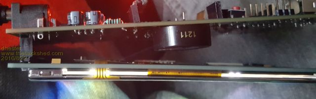
I tried a few things and found if the board is at an angle it works great.
I think it might be a faulty socket, I will get a different one and solder that in to see if that corrects the fault.
WhiteWizzard Guru Joined: 05/04/2013 Location: United KingdomPosts: 2991
Posted: 10:06am 22 Aug 2016
Copy link to clipboard
Print this post
@dhester,
It is not very easy to just solder in a new socket. Instead I would recommend running an iron and solder over all the pins of the 40-way connector (CON9) as there may be a 'bad' solder joint. Try this first; and also run an iron on the TFT pins too (many modules from eBay seen here have needed re-soldering!!!!)
Also ensure you use spacers between the TFT PCB and the E100 PCB. At least use a piece of cardboard if you have no spacers.
Glad it is working there for you but do let us know if you have any other issues.
WW
dhester Newbie Joined: 17/07/2016 Location: United KingdomPosts: 11
Posted: 10:33am 22 Aug 2016
Copy link to clipboard
Print this post
WW
Just afyer I worte the last post I suddenly thought it might be a faulty solder joint. I have already tested the joints on the connector I soldered so will "re solder" the LCD joints.
Again, thanks for all the assistance.
Phil23 Guru Joined: 27/03/2016 Location: AustraliaPosts: 1667
Posted: 11:55am 22 Aug 2016
Copy link to clipboard
Print this post
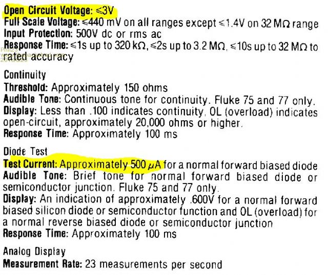
So I presume that means I shouldn't use the Continuity/Diode test mode on my old Fluke 77?
I'm probably guilty of poking around things in that mode due to the beeper.
Thanks
Phil.
Grogster Admin Group Joined: 31/12/2012 Location: New ZealandPosts: 9985
Posted: 03:18pm 22 Aug 2016
Copy link to clipboard
Print this post
@ dhester - the fact that it works at an angle PROVES there is definitely nothing wrong in terms of possible shorts on the PIC32 chip on the E100 board - phew! What this DOES prove, is that you have issues around the connector to the LCD, and as you have already suggested, perhaps a short or a bad soldering connection there. Normally, it just works, as you know I am sure. Ain't electronics fun!
@ Phil23 - Diode test mode is usually fine too, BUT it depends on the meter. Normally, the diode-test mode on most meters only allows a tiny current to flow, so is ideal, but that is not ALWAYS the case, as it depends on the meter. The manual for that meter will tell you what kind of current-limit the diode-test has. At the end of the day, so long as the E100 board is NOT powered, it should not really care, but PIC's are funny things, and they CAN(and do) actually try to power up via parasitic power from one of the I/O pins, so I always like to use rather strongly current-limited testing methods when poking around MCU I/O pins. This is just ME - by no means perhaps what others would do. Some may even say no special caution is needed, but this is just the way my brain works. Beeper mode on your meter is also fine, PROVIDED it is well current-limited and buffered inside the meter - the manual for the meter will also tell you this. If it doesn't, then assume it doesn't. Smoke makes things work. When the smoke gets out, it stops!
Phil23 Guru Joined: 27/03/2016 Location: AustraliaPosts: 1667
Posted: 07:36pm 22 Aug 2016
Copy link to clipboard
Print this post
Lol,
Would you believe I can actually find a manual for this meter....
Circa 1986.
Diode Test & Continuity are the same mode. 500�A.
Thanks.
mikeb Senior Member Joined: 10/04/2016 Location: AustraliaPosts: 180
Posted: 08:58pm 22 Aug 2016
Copy link to clipboard
Print this post
I used beeper mode. Geoff proved you can't destroy a PIC32. You just don't want to let the smoke out Grogs. There are 10 kinds of people in the world. Those that understand binary and those that don't.
Grogster Admin Group Joined: 31/12/2012 Location: New ZealandPosts: 9985
Posted: 10:35pm 22 Aug 2016
Copy link to clipboard
Print this post
@ Phil23 - Well done you, finding the manual! I did not know the meter was that old, so well done. With a 500 micro-amp test current, so you'd be fine using the diode test mode.
@ mikeb - Yes, I am scared of the secret smoke! It is damn hard to catch it all and get it back inside the chip again, you see....... Smoke makes things work. When the smoke gets out, it stops!
Phil23 Guru Joined: 27/03/2016 Location: AustraliaPosts: 1667
Posted: 01:06am 23 Aug 2016
Copy link to clipboard
Print this post
Be nice about my old meter, Cost me an arm & leg back in '86,($500+AU from memory).
Still well inside specs too.
I really don't need someone pushing me over the edge to buy the new toy I keep looking at...
Fluke 117? Be better on my eyes. Reasonable model & features?
Any opinions.
Phil.
Grogster Admin Group Joined: 31/12/2012 Location: New ZealandPosts: 9985
Posted: 01:31am 23 Aug 2016
Copy link to clipboard
Print this post
Oh, I was not being unkind about your old meter. The old ones show their reliablity - they are still going!
I was just thinking you had done well to still have or be able to find the manual.Smoke makes things work. When the smoke gets out, it stops!
dhester Newbie Joined: 17/07/2016 Location: United KingdomPosts: 11
Posted: 08:36am 23 Aug 2016
Copy link to clipboard
Print this post
Thanks to all you guys for the help.
I double checked all my soldering and remade the joints then the did the same on the lcds. Now everything works.
Just as an aside does anyone else feel they should use a mini keyboard when using a small board like the explore 100 or the MUP boards?
WhiteWizzard Guru Joined: 05/04/2013 Location: United KingdomPosts: 2991
Posted: 10:39am 23 Aug 2016
Copy link to clipboard
Print this post
I have a mini PS2 keyboard linked to the first Explore100 assembled a few weeks back. I have the E100 configured as a standalone system connected to a 7" TFT. It is permanently next to my main machine so that I can do any tests needed.
This is what I like very much about the MM+; ready to switch on and run a line of 'test code' within seconds. So my answer to your question is very much a YES to having a mini keyboard connected.
The PS2 keyboard is a MM+ 'feature' (i.e. 64pin & 100pin MMs only) and hence will not be immediately possible to connect one to a MuP.
WW
Page 1 of 3
Print this page
The Back Shed's forum code is written, and hosted, in Australia.


 . Look at his post first and do what he recommended. It is an excellent 'first off' method. You could probably do the same with ALL control signals to the LCD panel. Refer to the schematic in his 'Constructor' Pack. Probably worthwhile testing the LCD panel on something else if you have available. Or use another LCD panel. If you got LED's to blink, and the RTC to work, then your serial ports are obviously OK. Must admit I'm a bit 'taken aback' as to how you powered the board.

 What this DOES prove, is that you have issues around the connector to the LCD, and as you have already suggested, perhaps a short or a bad soldering connection there. Normally, it just works, as you know I am sure. Ain't electronics fun!