
|
|
Forum Index : Microcontroller and PC projects : NY Geothermal Controller I/O Pins
| Author | Message | ||||
| Paul_L Guru Joined: 03/03/2016 Location: United StatesPosts: 769 |
All of you guys were right! I'm running out of i/o pins. To refresh your recollection of this project I will be reading 16 DS18B20 temperature sensors in 11 bit resolution mode, running through some decision logic code, then controlling 12 output relays. I will also need 2 pins to monitor mains power and backup generator power, plus 6 pins for handshaking and data transfer between two potential uM+ cpus, plus pins to communicate with a RTC clock module, plus pins to communicate with an SD card, plus pins to display and read data from a touch screen. I'm not completely sure how many pins I will need. I think it works out like this: sensors 16 + power + ground = 18, relays 12, power sense 2, serial data 6, sd card 4, screen 6 for a total of 48 which I believe is too many pins. I have to find a way to reduce the number of i/o pins. My initial idea was to try to make this work using two Explore 64 modules, one to read the sensors, make decisions, and operate the relays, the second to display data and accept user input using a touch sensitive screen. I am reluctant to try to run groups of the DS18B20 sensors on a single pin, mostly because of the physical location of the sensors. They are spread out in all directions in a hub and spoke pattern with the most distant sensor about 40 feet from the cpu. Daisy chaining them together would increase the wire length to the most distant sensor. Question 1 - is there any way to use a separate "expander" circuit to drive the relays. Maybe something like a shift register to accept a serial input, decode its bits and drive the 12 relays, or even a smaller PIC chip, maybe a PICAXE? This could reduce the relay control pins from 12 to 2 or 3 handling serial data. Question 2 - would a single Explore 100 module do the job by itself? The problem here is that it would have to handle the GUI input functions while continuously processing the decision loop. How do the interrupt driven GUI functions work while they are waiting for a human to press the next input target? Will the main loop of the program continue to cycle through the sensor readings, decision making, and relay output settings without waiting for the slow motion human? If you think I can make it work with a single Explore 100 module I would loose the serial communication pins. Paul in NY. |
||||
Grogster Admin Group Joined: 31/12/2012 Location: New ZealandPosts: 9985 |
As to question #1, you could use a simple 74HC595 latch-driver circuit, combined with a ULN2003 relay driver. That would give you up to eight relays all of which could be controlled via a simple SPI channel(either native or via a Cfunction if you are already using your SPI channel). The beauty of the 595, is you can daisy-chain it if you wanted to, and add extra blocks of relays - you could have dozens all controlled via a simple three I/O pin SPI interface.(Data/Clock/Latch) Two of each will give you up to 16 relays, all separately addressable on a three-wire SPI interface. That is the cheapest way, as 595's and 2003's are cheap as chips, but there is nothing at all stopping you from having a separate PICAXE or other MCU dedicated to driving the relays. The practical upshot of using the 595/2003 idea, is that the 2003's provide the relay driving, whereas even if you use a PICAXE or other MCU to handle the relays, you will still need relay drivers for the I/O pins, be that discrete transistor buffer/drivers or the likes of a 2003. I have not built this circuit, but in theory, it should work fine. The 595 is commonly used to drive LED displays, and the 2003 is designed for driving relays, so by pairing up the two...... Smoke makes things work. When the smoke gets out, it stops! |
||||
| SiNut Newbie Joined: 12/03/2015 Location: United StatesPosts: 12 |
Hi Paul, I have used the MCP23S17 serial I/O expander to save pins on the processor. This device provides 16 I/O pins and its SPI interface requires four pins on the processor. The output of the MCP23S17 is connected to ULN2003A relay drivers. One expander and two of these relay drivers can handle up to 14 relays. Microchip also offers this expander with an I2C interface (part number MCP23017) which requires only two pins on the processor. You should be able to share the I2C interface on the uM+ between the RTC and this I/O expander. Both variants of the expander are available in DIP packages and are ~$1.50 from Mouser and Digikey. This is a simple and inexpensive turnkey solution. I hope this helps. -- G. Singh |
||||
| Phil23 Guru Joined: 27/03/2016 Location: AustraliaPosts: 1667 |
Hi Paul, I know it's not your desired solution but just for your information, the 7 DS18B20's I have running on a single pin are a combination of a bus with droppers & Star hub configuration at certain locations. All up I think I have around 40m of cable involved; all flat RJ-12 phone cables, a mix of 3 & 5 metre lengths with some 10's interconnecting. Very reliable. While you could probably get all 16 on one pin, I'd be inclined to maybe make 4 groups of 4; that would return 12 pins. Or alternatively have some in groups & keep super critical ones on their own pins. Cheers Phil. |
||||
| Phil23 Guru Joined: 27/03/2016 Location: AustraliaPosts: 1667 |
As another alternative to both issues of the Temp sensors and the Relays; A 28 Pinner could be used as an expander in a sense; Via Coms. You could use a single device solely to read the DS18B20's. You would have 17 I/O pins available once you sacrificed 2 pins for Com1. The same could apply for the relays. Other option would to be a similar approach with a 44 pin module. That would make 31 pins available for digital I/O once coms was used. Don't know if it's a good suggestion or not, but never hurts to think out loud. Phil. Edit:- I did consider moving both my Spa Controller & the Heat Pump controller to a single 64 pin device, but I'm preferring having 2 devices running, each with their own code. |
||||
mikeb Senior Member Joined: 10/04/2016 Location: AustraliaPosts: 180 |
@Phil, Personally, I think that's a great suggestion. Offload I\O and keep RTC, wifi and user interface on the main board. It would be worthwhile setting up the output board so it turns off the relays should regular refresh data not be received over the comms connection in a timely manner. There are 10 kinds of people in the world. Those that understand binary and those that don't. |
||||
| Paul_L Guru Joined: 03/03/2016 Location: United StatesPosts: 769 |
Is this something like what you are suggesting? I can't read the part numbers on this gadget. I don't know where this picture comes from or who sells this little board. 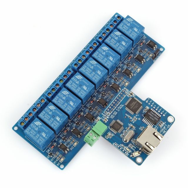
|
||||
| SiNut Newbie Joined: 12/03/2015 Location: United StatesPosts: 12 |
Hi Paul, The picture you have attached shows a relay board that is designed to be controlled over the Ethernet. It is made by SainSmart and you can find more information here: http://www.sainsmart.com/sainsmart-imatic-with-rj45-remote-control-8-channels-wifi-relay-kit-smartphone-android-ios.html I would not recommend using an Ethernet interface as it will add unnecessary complexity to your system. Using the I2C bus on the uM+ is a better choice. The MCP23017 I/O expander from Microchip will interface to the uM+ I2C bus and provide you with 16 additional I/O pins. With proper code on the uM+ the MCP23017 expander will operate these pins as outputs to drive the relays. You can use two 8-relay board from SainSmart and connect each one to eight output pins of the MCP23017 I/O expander. Here is a link to the details on the 8-relay board from SainSmart: http://www.sainsmart.com/8-channel-dc-5v-relay-module-for-arduino-pic-arm-dsp-avr-msp430-ttl-logic.html The 8-relay board has the necessary circuitry on it to drive the coils of the relays and also provide optical isolation between its inputs and the relay drivers - an added bonus. There is no need the ULN2003A devices I mentioned in my previous message. The input circuit of the relay board appears to be designed to operate on 5V. However the uM+ will be running at 3.3 volts as will the MCP23017. This lower voltage may not be sufficient to trigger the opto-couplers on the relay board. Short out the LEDs labelled IN1 on the relay board. This will eliminate their voltage drop from the input circuit and the opto-coupler will be able to operate with 3.3 volts input. I hope this helps. If you need more details please let me know. Regards, -- G. Singh |
||||
| Paul_L Guru Joined: 03/03/2016 Location: United StatesPosts: 769 |
The uM+ will most likely be located in a central wood frame wall on the ground floor. The seven room air sensors will be in different directions from this point and at distances ranging from 20' to 70'. These wire runs will go up into the attic and drop back down in other walls to the sensors. The longest wire run will be about 100' There will be a wire run of about 80' to an outside air temperature sensor mounted under a roof eave on the north side of the house. The six sensors near the heat pump will be in the basement nearly vertically below the uM+. The wire runs to them will be about 15'. I like the idea of using RJ-12 phone cables. What kind of female jacks have you used on the PCBs and on the short cable to the sensors themselves? Paul |
||||
| Paul_L Guru Joined: 03/03/2016 Location: United StatesPosts: 769 |
I just happened to have a couple of those relay boards hanging around. I don't really intend using them. I was thinking of using a higher quality plug in relay, probably Omron. The total relay coil current when operating 12 relays starts becoming significant. I plan on using 12vdc relay coils to reduce the required current. I planned on driving the relay coils with the ULN2003A darlington arrays with the freewheeling diode protection. The power supply will be a battery backed 12v with regulators dropping that to 3.3v for the uM+. Will the MCP23017 be able to drive the darlington arrays directly from the 3.3vdc source? Which part of this continent are you located in? Paul_L |
||||
| Phil23 Guru Joined: 27/03/2016 Location: AustraliaPosts: 1667 |
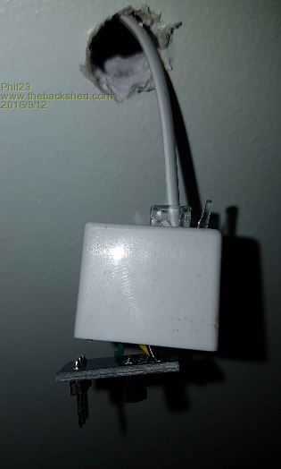
Hi Paul, This post will give you a rough idea of how I'm connecting things. It's really a mixed topology in my case, a mix of Star, bus & droppers. I've also seen some 4 way splitters on ebay for a few bucks. I've got enclosures to put the sensors in, they we a few bucks each also. 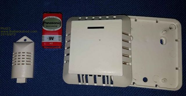
For the board end I think I'll cut off the RJ-12's & replace then with 3 pin polarised headers. Like these. 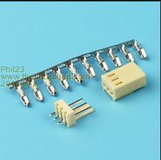
Phil. |
||||
| Phil23 Guru Joined: 27/03/2016 Location: AustraliaPosts: 1667 |
|
||||
| SiNut Newbie Joined: 12/03/2015 Location: United StatesPosts: 12 |
Hi Paul, By my estimation the MCP23017 running at 3.3 volts should be able to drive the ULN2003A without any problems. Here are the details. The specs of the ULN2003A darlington driver show that it requires an input current of 250uA to reach saturation while driving a load of 200 to 300 mA. This is more than adequate current for the coil of a 12 volt plug-in relay. With the MCP23017 running at 3.3 volts its GPIO pins are able to swing to 2.6 volts (3.3 - 0.7 volts per its spec). The input circuit of the ULN2003A has a 2.7K resistor in series with the Vbe junctions of the two transistors in darlington connection. The MCP23017 will drive 444uA into the ULN2003A ((2.6 - 2 * Vbe) / 2.7K ) which will turn on the device reliably. I hope this helps. I am located in the northwest US, just outside Seattle. -- G. Singh |
||||
| mikeb Senior Member Joined: 10/04/2016 Location: AustraliaPosts: 180 |
Well done G. Excellent use of datasheets. You can't do without them. There are 10 kinds of people in the world. Those that understand binary and those that don't. |
||||
| Paul_L Guru Joined: 03/03/2016 Location: United StatesPosts: 769 |
Nice analysis! Thanks! I guess I'll go with the MCP23017 driving ULN2003A darlington drivers and then the Omron plug in relays. The Omron relays are expensive but I think are justified considering that the heat pump I'm running cost a little over $6000. I'm not switching the compressor load current directly. Its locked rotor inrush current is 150 A at 240 vac. It is fed by a large noisy relay with 1/2" diameter plated contacts. An Omron relay will control 24 vac to this things coil. Other Omron relays will switch 120 vac feeding various water pumps and a 3/4 hp blower. Back in 1969 and 1970 I used to hang out in your part of the country when Pan Am was taking delivery of the first 24 B747 aircraft at Everett. Now I'm in the Hudson Valley 75 miles north of NYC. Paul_L |
||||
| SiNut Newbie Joined: 12/03/2015 Location: United StatesPosts: 12 |
Hi Paul, I can't agree more with buying quality relays for such an application. Good luck with the project and do give us updates on your progress. Boeing is a huge part of the economy here and it is always a treat to visit their production facility in Everett where they are still turning out a few B747s each year, alongside the much higher numbers of B777s and B787s. Engineering at its finest. -- Gurbir Singh |
||||
| The Back Shed's forum code is written, and hosted, in Australia. | © JAQ Software 2026 |
