
|
|
Forum Index : Microcontroller and PC projects : 7" SSD1963 TFT box and bezel for E100
| Author | Message | ||||
| matherp Guru Joined: 11/12/2012 Location: United KingdomPosts: 11608 |
Following on from this thread I've also designed and printed a bezel and matching box for the 7" SSD1963 display and Explore 100. Ignore the colour - just the filament I had available  Design files: 2016-10-05_175117_box7inch.zip 2016-10-05_150257_7inchbezel.zip 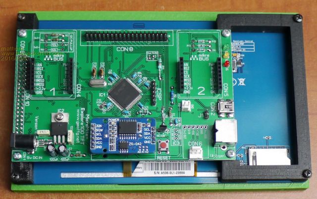 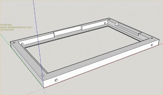 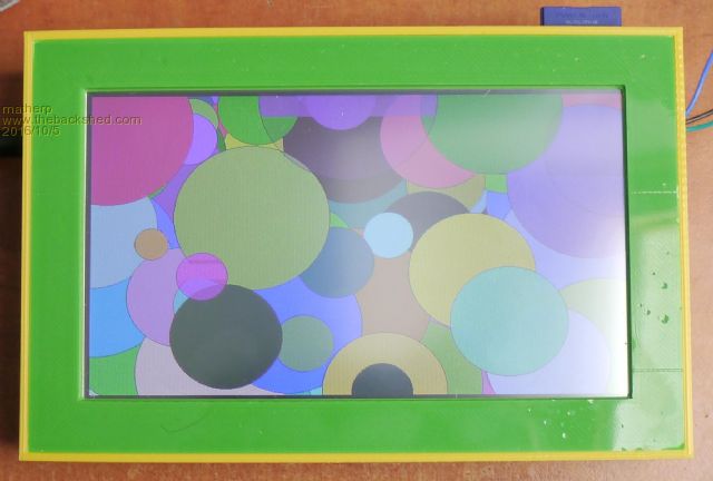 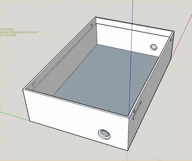 |
||||
| Zonker Guru Joined: 18/08/2012 Location: United StatesPosts: 772 |
Awesome Peter..! I will see if I can get Ed to print up a set and see if I can get the 7" fitted correctly.. A stable box of the E-100.. (nice)  Edit: I see the hole in the box for the power in jack and SDcard ... Whats the other hole for..? Is there maybe a slot for the I/O interface..? |
||||
| matherp Guru Joined: 11/12/2012 Location: United KingdomPosts: 11608 |
Any cables you need to connect to the outside - it is sized to take a 6mm ID rubber grommet. In my version I have a DS18B20 and a MCP3424 ADC breakout connected internally and double-sided taped to the back of the display and a pair of type-K thermocouples connected through the hole together with the serial port for development |
||||
disco4now Guru Joined: 18/12/2014 Location: AustraliaPosts: 1130 |
My Bezel Collection. 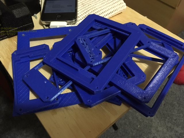 Inspired by Peter's original bezel for the 4.3 SSD1963 screen, I ordered and built a 3D printer and learned about OpenScad which is a mathematical/programing method of defining 3D images. Its a bit of an iterative process so I have bezels ready for any new obscure LCD sizes the Chinese come up with. Even a couple that fit existing ones. These are just the ones that got to a stage where it was worth seeing if they were close! Regards Gerry F4 H7FotSF4xGT |
||||
| disco4now Guru Joined: 18/12/2014 Location: AustraliaPosts: 1130 |
Here are the files for a 5" SSD1963, an STL 3D file and the OpenSCAD source file if anyone wants to play. 2016-10-07_094324_Customizable_Enclosure_5inchssd1963.zip Regards Gerry F4 H7FotSF4xGT |
||||
| panky Guru Joined: 02/10/2012 Location: AustraliaPosts: 1130 |
Peter, Have you done a design for your MM+ 470 board that Circuit Gizmos sell? I don't have a 3D printer but do have a need for two 5" spacer/bezel/box items and two 7" spacer/bezel/boxes, both for use with your 470 board. Am happy to pay anyone who could print them up for me. Cheers, Doug. ... almost all of the Maximites, the MicromMites, the MM Extremes, the ArmMites, the PicoMite and loving it! |
||||
| Paul_L Guru Joined: 03/03/2016 Location: United StatesPosts: 769 |
Peter, This case design is nice work! Do you think it would be practical to provide rectangular cutouts in the sides so that RJ plugs (probably 8P8C) could be plugged into sockets mounted on a PCB just inside of the cutouts? I anticipate needing to house a 7 inch or larger display coupled to an E100 assembly and to a mother board which would carry the RJ jacks on one edge. What CAD software did you use to design this case? Thanks, Paul |
||||
| matherp Guru Joined: 11/12/2012 Location: United KingdomPosts: 11608 |
I use Sketchup. The design files are in the ZIP and can easily be modified to change the holes in the box. Be aware the box is 190mm wide so you need a printer capable of a true 200mm width to print it |
||||
| The Back Shed's forum code is written, and hosted, in Australia. | © JAQ Software 2026 |
