
|
|
Forum Index : Microcontroller and PC projects : Micromite EXTREME TFT Backpack
| Author | Message | ||||
| matherp Guru Joined: 11/12/2012 Location: United KingdomPosts: 8584 |
All feedback appreciated before I go to copper. I will of course post the gerbers as soon as I'm happy they are OK 2016-11-26_104639_Schematic.pdf 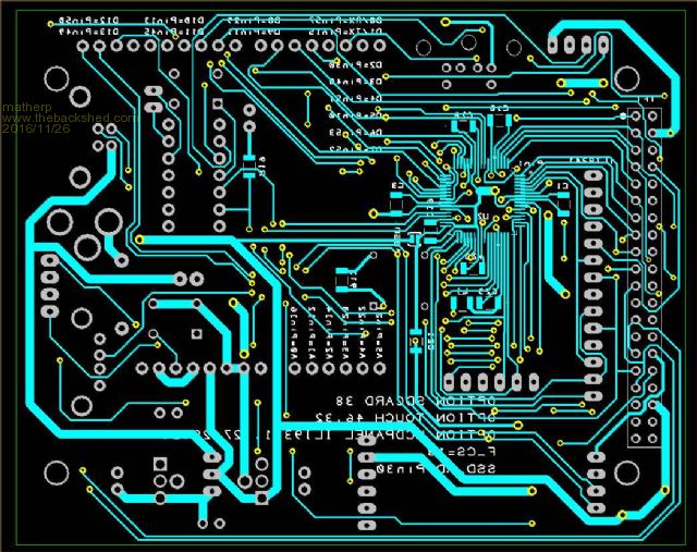 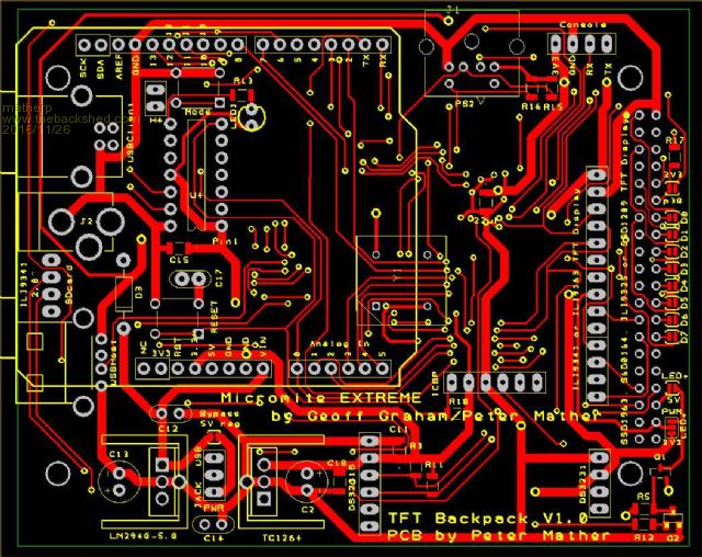 Power selectable from 2.1mm power jack (7.5-12V) or either USB connector 5V (optional) and 3.3V linear regulators Independent PIC16F1454 USB Console with Micromite firmware update capability USB connection for using Micromite EXTREME in-built USB console connection Standard DIP 12 or 24MHz Oscillator Headers: DS3231 RTC Module Console ICSP ILI9341 TFT display (including SD card pins for 2.8" version) SSD1963, SSF1289, ILI9325 or S6D0164 TFT displays Arduino header gives access to: A0 - Pin 13 Analog / Digital / COM2-RX / SPI4-IN A1 - Pin 12 Analog / Digital A2 - Pin 14 Analog / Digital / COM1-EN / SPI4-OUT A3 - Pin 23 Analog / Digital / COUNT A4 - Pin 22 Analog / Digital /SPI3-IN A5 - Pin 21 Analog / Digital D0 - Pin 57 Digital / 5V / COM1-RX D1 - Pin 15 Analog / Digital / COM1-TX D2 - Pin 30 Analog / Digital / PWM-2B D3 - Pin 48 Digital / PWM-1A D4 - Pin 51 Digital / 5V / COUNT D5 - Pin 10 Analog / Digital / PWM-1C D6 - Pin 53 Digital / 5V / PWM-2A D7 - Pin 52 Digital / 5V / COUNT D8 - Pin 29 Analog / Digital / PWM-1B / SPI3-CLK D9 - Pin 11 Analog / Digital / COM2-TX / SPI3-OUT D10 - Pin 13 Analog / Digital / COM2-RX / SPI4-IN D11 - Pin 45 Digital / 5V / SPI1-OUT D12 - Pin 50 Digital / 5V / SPI1-IN D13 - Pin 49 Digital / 5V / SPI1-CLK D14 - Pin 43 Digital / 5V / I2C-SDA D15 - Pin Digital / 5V / I2C-SCK / SPI4-CLK |
||||
| WhiteWizzard Guru Joined: 05/04/2013 Location: United KingdomPosts: 2794 |
Looks nice, and really useful!  My comments/questions: 1> What are the mm dimensions of PCB? 2> The mounting holes look very close to 'things' - may not allow screw heads/bolts to be used? 3> Is there an onboard uSD socket - can't see one - but my eyes are going bonkers looking at this! 4> How many PCBs would you get made? I am happy to offer these as part/fully assembled - so possibly bring down PCB manufacture unit cost for you. 5> Could you send me larger format diagram to save my eyes? 6> How soon?  7> Any chance of a 100pin version too  WW For everything Micromite visit micromite.org Direct Email: whitewizzard@micromite.o |
||||
| WhiteWizzard Guru Joined: 05/04/2013 Location: United KingdomPosts: 2794 |
Could you make the console a 5-way by adding a 5v pin? I know this could add 'power issues', but smart use of jumpers can resolve this. The reason for asking is that the unit could then be powered by a single cable/connection to the console header. Just a suggestion . . . For everything Micromite visit micromite.org Direct Email: whitewizzard@micromite.o |
||||
| matherp Guru Joined: 11/12/2012 Location: United KingdomPosts: 8584 |
100x80 I've now improved this for at least three of the holes. The holes match the 3.2" SSD1289 display. Anything bigger breaks the 10x10 limit for v-cheap PCBs No, the expectation is that the SDsocket on the TFT display is used and the wiring supports this 2016-11-26_170941_Bottom.pdf 2016-11-26_170953_TOP.pdf As soon as Itead make the PCbs Not on the agenda at the moment. easy to mod the schematic but the layout on double sided takes forever. Done |
||||
| WhiteWizzard Guru Joined: 05/04/2013 Location: United KingdomPosts: 2794 |
Thanks for your responses Peter. One thing I recommend; try giving PCB GoGo a try for the PCBs. I used to use itead but can strongly recommend GoGo. They are much quicker (to land) and are generally cheaper. Quality is as good, if not better, than iTead so a definite win-win. GoGo record from ordering to landing is 4 days! Typically 7 days, but it is now nearer Christmas so may take about a week+. WW For everything Micromite visit micromite.org Direct Email: whitewizzard@micromite.o |
||||
| WhiteWizzard Guru Joined: 05/04/2013 Location: United KingdomPosts: 2794 |
Can't follow the OSC circuit. Seems like C19 is between pins 31 and 30. Is this meant to be like that? Where is the oscillator located on you PCB? Just can't see it even on the bigger format! Likely to be me missing it, but just raising it . . .. For everything Micromite visit micromite.org Direct Email: whitewizzard@micromite.o |
||||
| matherp Guru Joined: 11/12/2012 Location: United KingdomPosts: 8584 |
You are probably looking for something small - it is huge (comparatively) big square box with 4 pins at the corners labelled Y1 on the top diagram RS 796-0619 |
||||
| WhiteWizzard Guru Joined: 05/04/2013 Location: United KingdomPosts: 2794 |
Have you purchased all their stock? RS currently have none available  Sure did miss that Y1. What does the 'Y' prefix signify? For everything Micromite visit micromite.org Direct Email: whitewizzard@micromite.o |
||||
| panky Guru Joined: 02/10/2012 Location: AustraliaPosts: 1094 |
Great job Peter, I have 4 of your 470 boards (through Circuit Gizmos), two made up and working fine with two more to build. The 470 boards are really solid design and were quite straight forward to assemble and this looks just as good. Would love to get my hands on a couple of your MZ bare boards above from anyone doing a buy. WW? Regards, Doug. ... almost all of the Maximites, the MicromMites, the MM Extremes, the ArmMites, the PicoMite and loving it! |
||||
palcal Guru Joined: 12/10/2011 Location: AustraliaPosts: 1802 |
I suppose it is too late to change the console pins around so a HC-12 would plug in. Paul. "It is better to be ignorant and ask a stupid question than to be plain Stupid and not ask at all" |
||||
| matherp Guru Joined: 11/12/2012 Location: United KingdomPosts: 8584 |
What is the pinout? I've never seen or used one. |
||||
| WhiteWizzard Guru Joined: 05/04/2013 Location: United KingdomPosts: 2794 |
1> Vcc (3v2 - 5v0) 2> GND 3> HC12 RxI 4> HC12 TxO 5> (Set) However, unfortunately this is not a 'standard' pin-sequence in the HC range of modules. So what sequence is good for one HC module is not good for another! WW For everything Micromite visit micromite.org Direct Email: whitewizzard@micromite.o |
||||
| palcal Guru Joined: 12/10/2011 Location: AustraliaPosts: 1802 |
Not to worry I can make an adapter. Paul. "It is better to be ignorant and ask a stupid question than to be plain Stupid and not ask at all" |
||||
disco4now Guru Joined: 18/12/2014 Location: AustraliaPosts: 844 |
Hi Peter, Its probably a bit late and may not fit, but would it be possible to duplicate the Arduino header pins that are offset by half a hole so the second set is lined up on a normal hole position. This would allow you to use veroboard as well as the arduino shield.  Latest F4 Latest H7 |
||||
| Phil23 Guru Joined: 27/03/2016 Location: AustraliaPosts: 1664 |
100% Agree Disco. I was about to make the same suggestion, but you beat me to it. At least I'm glad I'm not the only one that thinks that way. The Arduino pin offset is always a pain for those of us who build finished project on proto-board. Usually after it living for some months on a Solder-less board. Phil |
||||
| matherp Guru Joined: 11/12/2012 Location: United KingdomPosts: 8584 |
Please note that the 64-pin part is not being supported by my code anymore. We have swapped to the 100 and 144 pin variants for the MZ (see this thread ) so this design is now obsolete. |
||||
