
|
|
Forum Index : Microcontroller and PC projects : Bedside clock
| Author | Message | ||||
| yobortsa Newbie Joined: 12/12/2011 Location: AustraliaPosts: 37 |
Project overview if anybody interested. Bedside clock - I got sick of all the clocks in the house being out of time. So this one syncs to Internet time every 60 seconds over a CAN bus. And it has an alarm (just a piezo at the moment) that lets me know it's 6am on a weekday. Doesn't come on on weekends. 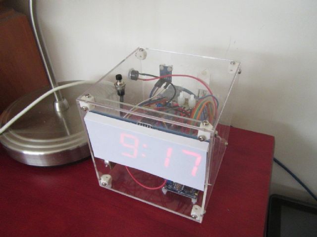 CAN bus is great for sensors - as long as you don't saturate the bus, you can send any time you like and the data will go through. The transmission automatically drops out if the driver detects another unit clashing with the transmission. No more master/slave RS485 arrangements - just send when you want to and if other stations want the data they can run with it... I use the same CAN bus to run our security system - PIRs send CAN packets whenever movement is detected in a zone. There is an Arduino interface module between the CAN bus and the Server - basically a CAN to USB Serial adapter. So I threw in a few sensors: 1. DHT22 for temperature/humidity 2. BMP085 for pressure/temperature 3. Luminance to adjust brightness of display All parts sourced cheaply on eBay. 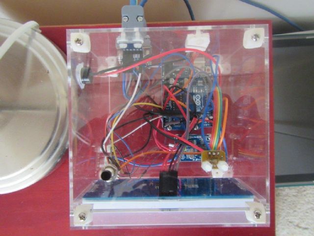 I made box on laser cutter and fabricated the corner joiners on 3D printer (tapped them to M3 after printing). I use OpenSCAD for 3D modelling - a bit of a learning curve but fantastic and simple if you like programming. 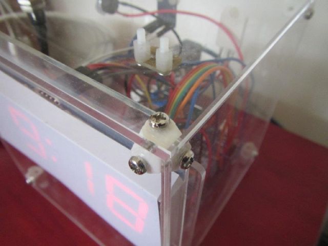 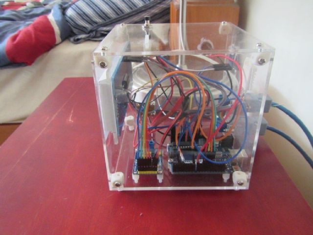 I'm logging the data to a MySQL database every minute. Here is the latest data which is available live to me via my webserver in PHP using JPGraph (I probably should adjust the bottom margin so you can see the full date). Will also move it over to a FLOT JavaScript chart at some stage too. 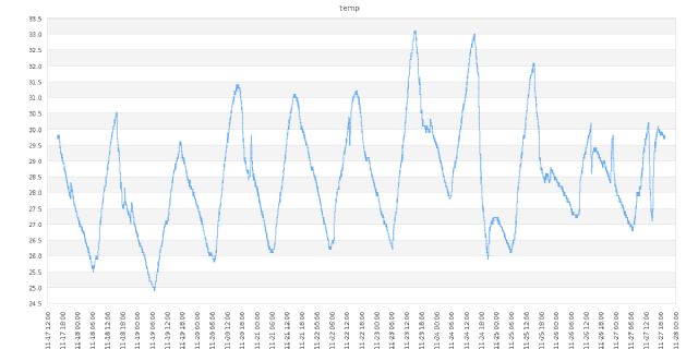 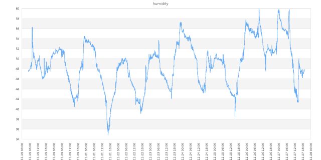 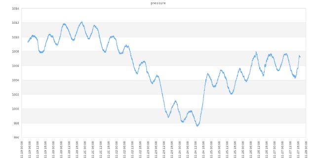 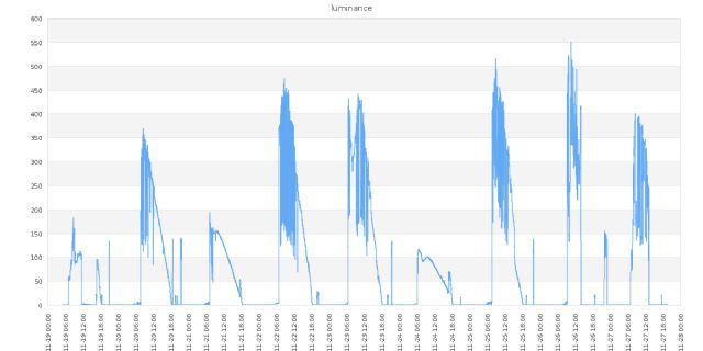 |
||||
| panky Guru Joined: 02/10/2012 Location: AustraliaPosts: 1127 |
Very interesting project David. Do you have a circuit diagram or block diagram of your setup that you are willing to share? Which of the 'mites are you using? Doug. ... almost all of the Maximites, the MicromMites, the MM Extremes, the ArmMites, the PicoMite and loving it! |
||||
Grogster Admin Group Joined: 31/12/2012 Location: New ZealandPosts: 9973 |
@ Doug - looks like he's using an Arduino. Smoke makes things work. When the smoke gets out, it stops! |
||||
| paceman Guru Joined: 07/10/2011 Location: AustraliaPosts: 1329 |
What did you use for the luminance sensor David? Also, did you mount the sensors inside the box or outside. Greg |
||||
| yobortsa Newbie Joined: 12/12/2011 Location: AustraliaPosts: 37 |
Here is a block diagram showing the basic setup of the units connected by Cat5 cable with DB9 connectors (in and out on each unit): 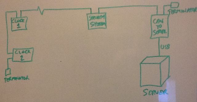 The total run is about 30 metres I guess and carries 12V power as well as the CAN bus on a single Cat5 cable. Good spotting Grogster - yep, all driven by Arduinos with an SPI MCP2515 based CAN Bus Module that uses a TJA1050 transceiver. Not bad for $2.86 including delivery: MCP2515 from eBay It would be very easy to set up a similar system using the Micromite. I'm using the Freetronics Light Sensor Module for reading luminance at the moment. All the sensors are installed inside the box but I laser cut openings for each of them to protrude through (apart from the light sensor which sees through the clear acrylic). Happy to share more details if people are interested - just ask! Regards, David |
||||
| yobortsa Newbie Joined: 12/12/2011 Location: AustraliaPosts: 37 |
Here are the laser cut parts: 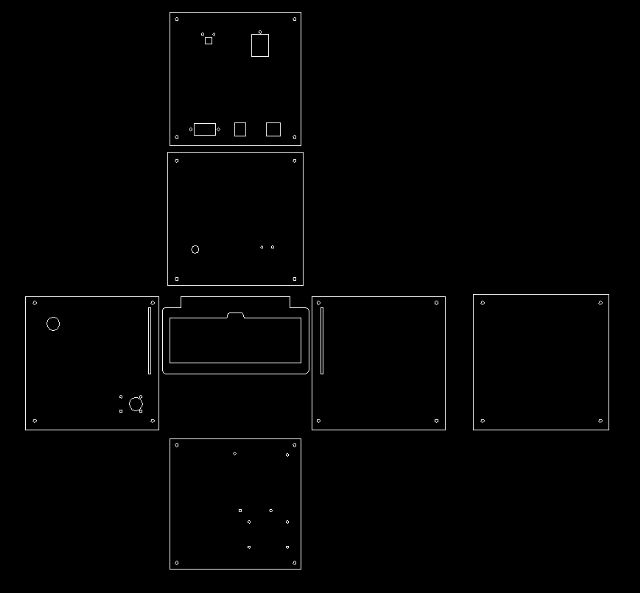 And the corner brackets that I 3D printed then tapped to M3 thread: 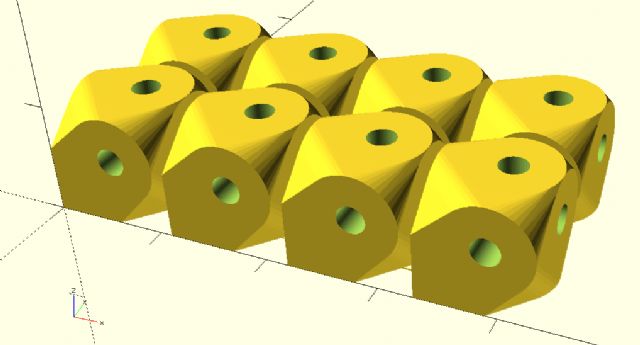 Here is the OpenSCAD program I created that produced the 3D model for these brackets: fineness=50; holein=6; od=8; id=2.5; // 2.5mm = tap size for M3 x 0.5mm thread or=od/2; ir=id/2; depth=10; translate([depth*0+0, 0, 0]) bracket(); translate([depth*1+1, 0, 0]) bracket(); translate([depth*2+2, 0, 0]) bracket(); translate([depth*3+3, 0, 0]) bracket(); translate([0, depth*1+1, 0]) { translate([depth*0+0, 0, 0]) bracket(); translate([depth*1+1, 0, 0]) bracket(); translate([depth*2+2, 0, 0]) bracket(); translate([depth*3+3, 0, 0]) bracket(); } translate([0, -2+depth/2, 0]) cube(size=[depth*4, 0.1, 0.1]); translate([0, -1+depth+depth/2, 0]) cube(size=[depth*4, 0.1, 0.1]); translate([-2+depth/2, 0, 0]) cube(size=[0.1, depth*2, 0.1]); module bracket(){ difference(){ hull(){ translate([holein,0,holein]) rotate(a = [-90, 0, 0]) socket(); translate([0,holein,holein]) rotate(a = [0, 90, 0]) socket(); translate([holein,holein,0]) socket(); translate(0.01,0.01,0.01) cube(size = [holein, holein, holein], center = false); } translate([holein,0,holein]) rotate(a = [-90, 0, 0]) hole(); translate([0,holein,holein]) rotate(a = [0, 90, 0]) hole(); translate([holein,holein,0]) hole(); } } module socket() { cylinder(h=depth, r1=or, r2=or, centre=false, $fn=fineness); } module hole() { translate([0, 0, -1]) cylinder(h=depth+2, r1=ir, r2=ir, centre=false, $fn=fineness); } |
||||
| yobortsa Newbie Joined: 12/12/2011 Location: AustraliaPosts: 37 |
And of course the large 7 segment LED displays (I2C) were from eBay also at about $13ea. They were a bit bright for my liking even on the lowest dimming setting so I put a piece of paper between them and the acrylic front of the box. Not a very high-tech solution, but it works! |
||||
| JohnS Guru Joined: 18/11/2011 Location: United KingdomPosts: 4332 |
Looks kinda fun. Which Arduino board is it? What sort of code size? (Post it if you like.) Is CAN over Cat5 reliable? (I'm tempted.) Is it 12V DC or AC (I'm guessing DC)? John |
||||
| yobortsa Newbie Joined: 12/12/2011 Location: AustraliaPosts: 37 |
Hi John, I'm using regular Arduino UNO boards from eBay. Find attached a copy of the code for the clock. 2016-11-28_193655_can_clock_plus.zip It relies on a few libraries: 1. Adafruit LED display 2. BMP085 - pretty sure these are in the standard Arduino IDE these days 3. DHT22 - pretty sure these are in the standard Arduino IDE these days 4. CAN bus MCP2515 (I think this is the one) 5. Time library (to convert from unixtime; I think this is the one) Regards, David |
||||
| yobortsa Newbie Joined: 12/12/2011 Location: AustraliaPosts: 37 |
And here is the code for the CAN bus to USB Serial interface for the Arduino (same board as last post): 2016-11-28_195549_can_to_serial_interface.zip It just relies on the CAN bus MCP2515 library. It sends all received packets to the Serial port at 115,200 baud and transmits CAN packets on the CAN bus received in the format: address,byte1,byte2,byte3,byte4,byte5,byte6,byte7,byte8<enter> I've come up with a protocol for the CAN bus transfers - CAN bus addresses below 0x0f are considered broadcast addresses so processed by all units. Anything address above 0x0f is dedicated to sensors and devices. Each one has a base address and an optional number of addresses base address+offset for sending data back. I use a PHP script on the server to listen on the Serial port and save the data in a MySQL database. It also listens on a TCP port for incoming connections so I can monitor what's coming in. It also allows me to send CAN bus packets easily from anywhere. Regards, David |
||||
| JohnS Guru Joined: 18/11/2011 Location: United KingdomPosts: 4332 |
Interesting! Makes a change to see a non-MMBasic/non-PIC32 project. John |
||||
| yobortsa Newbie Joined: 12/12/2011 Location: AustraliaPosts: 37 |
Yeh, a bit hard to keep up with it all these days. We use mainly STM32 processors at work, I use a mix of Atmel and PIC at home. And programming is a mix of C (Windows, Linux and embedded), Basic, PHP, MySQL, JavaScript (incl Node.JS) and Delphi running on a host of platforms that are getting more and more complicated with virtualization and the likes of Docker. |
||||
| The Back Shed's forum code is written, and hosted, in Australia. | © JAQ Software 2026 |
