
|
|
Forum Index : Microcontroller and PC projects : Micromite EXTREME b3b4: 16-bit displays
| Author | Message | ||||
| matherp Guru Joined: 11/12/2012 Location: United KingdomPosts: 11424 |
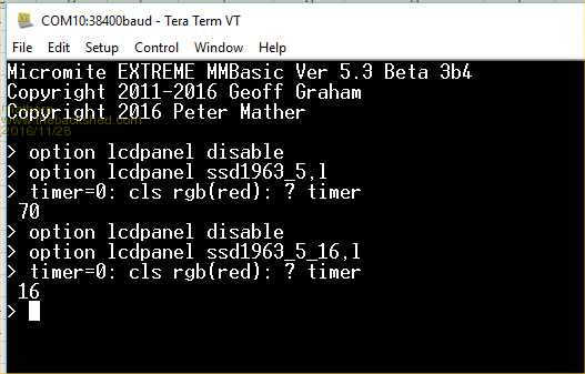 This release implements the new pinout for the 100-pin MZ and also includes 16-bit versions for all the variants of the SSD1963 displays. To use the 16-bit driver just add "_16" to the display type in the OPTION command as per the screen shot. The 16-bit drivers are not available on the 64-pin parts. The advantage is the driver is MUCH faster. The disadvantage is that it uses more pins and is RGB565 rather than RGB888. The display pins DB8-DB15 are connected to pins B8-B15 in the list below. There is no change to the pinout of the 64-pin MZ other than pin 38 being excluded from general use as it is dedicated to USB. The pinout of the 100-pin part is the same as posted here with the exception that RX and TX have been reversed on COM3 as per Chronic's request. Subject to any bug fixes this completes the port of MMBasic 5.3b3 and includes the key functionality I wanted to achieve to allow operation at much higher speed (CPU and display) and greater accuracy (double precision floating point). I'm open to suggestions for enhancements but these should be things that specifically take advantage of the high performance platform rather than things which Geoff may or may not choose to include in the MX470. In general my intent is that the code will stay completely compatible with the MX470. i.e. anything which runs on the MX470 will also run on the MZ with no changes (other than pin allocations). The above test was run on a Snadpic MZ board but note the Snadpic regulators are not capable of powering a 5" or 7" display properly so I'm using an external 3.3V supply connected direct to the display with a common ground. The command to use the Snadpic on-board SDcard is: OPTION SDCARD 4,81,59 as it is connected to SPI channel 4 and uses 81 for CS and 59 for CD 2016-11-28_172718_MicromiteExtremeb3b4-12MHz.zip 2016-11-28_172738_MicromiteExtremeb3b4-24MHz.zip 1 G15 Analog 2 A5 Analog 3 E5 Analog 4 E6 Analog 5 E7 Analog 6 C1 Analog COUNT 7 C2 Analog COUNT 8 C3 Analog COUNT 9 C4 Analog COUNT/IR 10 G6 Analog SPI2-CLK 11 G7 Analog I2C-SDA 12 G8 Analog I2C-CLK 13 VSS 14 VDD 15 MCLR 16 G9 Analog PWM1C 17 A0 Analog 18 E8 Analog 19 E9 Analog 20 B5 Analog SSD1963-D5 21 B4 Analog SSD1963-D4 22 B3 Analog SSD1963-D3 23 B2 Analog SSD1963-D2 24 B1 Analog SSD1963-D1 25 B0 Analog SSD1963-D0 26 B6 Analog SSD1963-D6 27 B7 Analog SSD1963-D7 28 A9 Analog 29 A10 Analog 30 AVDD 31 AVSS 32 B8 Analog B8 33 B9 Analog B9 34 B10 B10 35 B11 Analog B11 36 VSS 37 VDD 38 A1 Analog 39 F13 Analog COM1-EN/SPI3-CLK 40 F12 Analog PWM2B 41 B12 Analog B12 42 B13 Analog B13 43 B14 Analog B14 44 B15 Analog B15 45 VSS 46 VDD 47 D14 Analog COM1-RX 48 D15 Analog COM1-TX 49 Oscillator 50 C15 51 VBUS 52 VDD 53 VSS 54 D- 55 D+ 56 F3 USBID 57 F2 COM3-TX 58 F8 COM3-RX 59 A2 Snadpic-SD-CD 60 A3 61 A4 62 VDD 63 VSS 64 F4 SPI3-IN 65 F5 SPI3-OUT 66 A14 SPI2-OUT 67 A15 SPI4-OUT 68 D9 69 D10 SPI4-CLK 70 D11 SPI4-IN 71 D0 PWM1B 72 C13 SPI2-IN 73 C14 PWM1A 74 VDD 75 VSS 76 D1 SPI-CLK 77 D2 SPI-IN 78 D3 SPI-OUT 79 D12 80 D13 81 D4 Snadpic-SD-CS 82 D5 PWM2A 83 VDD 84 VSS 85 F0 COM4-TX 86 F1 COM4-RX 87 G1 COM2-TX 88 G0 COM2-RX 89 A6 KBD-CLK 90 A7 KBD-DAT 91 E0 92 VSS 93 VDD 94 E1 95 G14 SSD1963-RESET 96 G12 SSD1963-RS 97 G13 SSD1963-WR 98 E2 99 E3 100 E4 Analog |
||||
f1fco Senior Member Joined: 18/03/2012 Location: FrancePosts: 155 |
thank you Peter ! what a fine work !!! is it a color VGA output in your mind ? another question, more realist : what pin for console rx and tx ? Pierre. 73s de F1FCO |
||||
| matherp Guru Joined: 11/12/2012 Location: United KingdomPosts: 11424 |
Console is the same as COM4, same concept as the MX470 |
||||
| f1fco Senior Member Joined: 18/03/2012 Location: FrancePosts: 155 |
sorry ! console is same pin as COM4 : tx on pin 85 and rx on pin 86 Pierre. 73s de F1FCO |
||||
| WhiteWizzard Guru Joined: 05/04/2013 Location: United KingdomPosts: 2977 |
Peter, Just out of interest, kiiid's Grain Benchmark has dropped from 4242 to 4138 with this latest release.  Is that something you would have expected? I can assure you everything else is exactly the same: OPTION BAUDRATE 115200 OPTION SDCARD 2,12 OPTION DISPLAY 30,100 Using console pins (i.e. not USB D+/D-) EDIT: Should mention that this is on the 64 pin MZ on kiiid's PCB (12MHZ version) |
||||
| matherp Guru Joined: 11/12/2012 Location: United KingdomPosts: 11424 |
I think you are over analysing, it could be just tiny changes in the way the compiler optimises with small code changes On the 200MHz Snadpic (24MHz) crystal it seems to have got faster with the same release - I'm now getting 4350 |
||||
| MicroBlocks Guru Joined: 12/05/2012 Location: ThailandPosts: 2209 |
Why not use the build in PMP or EBI device to connect to a LCD. Both support 8 bit and 16 bit. These peripherals are specifically made to support parallel connections like an LCD. They also support DMA which could even increase the speed more. Microblocks. Build with logic. |
||||
Grogster Admin Group Joined: 31/12/2012 Location: New ZealandPosts: 9973 |
Awesome.  Nice work, Peter. Would be interested to here the reply to MicroBlock's question above, but I expect there is probably a reason...... Smoke makes things work. When the smoke gets out, it stops! |
||||
| matherp Guru Joined: 11/12/2012 Location: United KingdomPosts: 11424 |
It would require a complete re-write and another different pinout It needs the image data to be prepared as a block of memory rather than created on the fly It wouldn't be much faster, if at all, the current code already operates at peripheral bus speed for block writes and because the data doesn't need to be pre-prepared there are savings in preparation time. Note that CLS is currently writing at 48,000,000 bytes per second including the Basic interpreter overhead! MicroBlocks' approach is ideal IFF you have a complete framebuffer in processor accessible memory. Then the write in the program is to the frame buffer and the DMA can send that to the display in the background. Even with the MZ we don't have enough on-chip memory for a complete framebuffer. To do this "properly" you would have external memory on the EBI for use as a framebuffer and DMA that direct to the screen via PMP. Easy enough to do but no longer a single chip solution and you really need the 144-pin chip to get enough pins. |
||||
| MicroBlocks Guru Joined: 12/05/2012 Location: ThailandPosts: 2209 |
Sure the most complicated use is with a frame buffer, this would require an LCD in RGB mode. A much easier way to use it is to use it as a peripheral that outputs data AND controls signals like RD/WR, EN, A0/A1. PMP is even used with graphical 2/4 line displays. Outputting data to an LCD in parallel mode is the same. Just put PMP in 8-bit or 16-bit mode and write/read the data. It is just like writing/reading from PORTB. A 'complete re-write' would be minimal as the only change is to use the PMP peripheral instead of PORTB. The thing is, when using the PMP peripheral to connect an LCD you open up the road for more sophisticated use of the LCD. Drawing a line for instance can be optimized, even small images(sprites) could be written to the display as sequence of data without the need to wait for it to complete. Lots of other possibilities are opened up, even small video sequences. When using the PMP in its simplest form it is just as easy to use as a PORT. The difference is that the PMP pins are then reserved for LCD use and without change in the hardware it can be used to control LCD's in very efficient ways. As this is now in the development stage and pins are reserved for functionality i think it is the best time to consider it, as in the future it will be much harder to change and all hardware that has been developed in the meantime can not be easily used when PMP is desired. Also as PMP has an address bus it would be possible to attach multiple LCD's enabling a whole new range of projects. Microblocks. Build with logic. |
||||
| matherp Guru Joined: 11/12/2012 Location: United KingdomPosts: 11424 |
PMP uses many of the PPS pins which would not leave enough on a 100-pin chip for all the other functions No it can't. The existing code already optimises this to the maximum extent possible: Set the screen area, load the colour, toggle WR until the area is filled. PMP would be slower as it can't know that it doesn't need to load the colour register for each pixel. If you want to convert the code I'm happy to send you the project to work with. |
||||
| MicroBlocks Guru Joined: 12/05/2012 Location: ThailandPosts: 2209 |
Researching this some time ago i had this conclusion: PMP uses 5 relocatable pins when used in 8 bit mode and 12 when in 16 bit mode. Using PORTB uses 7 relocatable pins when used in 8 bit mode and 13 in 16 bit mode. Using PORTB in 16 bit mode also prevents the SPI3 peripheral as the SCK3 on pin 43 is not relocatable. I would be happy to take a look, but unfortunately time does not permit to do much work on it at the moment. October - May is the busiest time for me. Microblocks. Build with logic. |
||||
| isochronic Guru Joined: 21/01/2012 Location: AustraliaPosts: 689 |
The DA will be released soon - no doubt with whiz-bang graphics - maybe best to see what that brings or chops out |
||||
boss Senior Member Joined: 19/08/2011 Location: CanadaPosts: 268 |
144pin MZ Snadpic board As I chatted yesterday with Mounir Dlima we should have the opportunity (hopefully in near future) to order even 144pin version of Snadpic MZ board Bo |
||||
| The Back Shed's forum code is written, and hosted, in Australia. | © JAQ Software 2026 |
