
|
|
Forum Index : Microcontroller and PC projects : Micromite EXTREME b5v6, VGA
| Page 1 of 4 |
|||||
| Author | Message | ||||
| matherp Guru Joined: 11/12/2012 Location: United KingdomPosts: 11388 |
This release includes full 640x480 VGA capability for both the 64 and 100-pin MZ parts. Note this requires a 24-MHz oscillator and going forward I will only be supporting 24-MHz oscillators for the EXTREME as these give full 200MHz capability. If you have a PCB with a 12MHz oscillator these can be easily swapped with a heat gun. I used RS part number 667-6338. 2016-12-07_155919_MicromiteEXTREMEb5v6.zip use: OPTION LCDPANEL VGA to enable the display, then OPTION LCDPANEL CONSOLE 1 will give a 80x36 line display for the console with full colour editing capability. All Micromite-PLUS drawing and GUI commands are available as per a TFT display On the 64-pin part only SPI2 is available for general use (including SDcard) if VGA is enabled. Other changes: TRIANGLE command implemented. Syntax is: TRIANGLE x1, y1, x2, y2, x3, y3 (, outline-colour (, fill-colour)) SPI4 commands and functions removed. SPI3 commands and function use the pins previously allocated for SPI4 MM.DEVICE$ now returns "Micromite Extreme" For SnadPIC SD card now use: OPTION SDCARD 3,81,59 Note Change to pinout of COM1-TX on 100-pin chip RANDOMIZE command removed The MZ has a hardware random number generator so doesn't need this command VGA Wiring: The wiring for VGA operation is exactly the same in concept as the Colour Maximite. Note the way that a diode to ground limits the RGB voltages to one diode drop (c0.7V) to meet the VGA specification. VGA connector pin 1: connect to VGA-RED-OUT via diode to GND and 120ohm resistor VGA connector pin 2: connect to VGA-GRN-OUT via diode to GND and 120ohm resistor VGA connector pin 3: connect to VGA-BLU-OUT via diode to GND and 120ohm resistor VGA connector pins 5, 6, 7, 8, 10: connect direct to GND VGA Connector pin 13: connect direct to: VGA-RED-SS, VGA-GRN-SS, VGA-BLU-SS, VGA-HSYNC VGA Connector pin 14: connect direct to VGA-VSYNC Micromite pins VGA-RED-CLK, VGA-GRN-CLK, VGA-BLU-CLK MUST be left unconnected. 64-pin pinout 1 E5 Analog / Digital / SSD1963-D5 2 E6 Analog / Digital / SSD1963-D6 3 E7 Analog / Digital / SSD1963-D7 4 G6 Analog / Digital / SPI2-CLK 5 G7 Analog / Digital / SPI2-OUT 6 G8 Console-RX / COM4-RX 7 VSS 8 3.3V 9 MCLR / 5V 10 G9 Analog / Digital / PWM-1C 11 B5 Analog / Digital / COM2-TX / VGA-RED-OUT 12 B4 Analog / Digital /VGA-VSYNC 13 B3 Analog / Digital / COM2-RX / SPI4-IN 14 B2 Analog / Digital / COM1-EN / SPI4-OUT / VGA-GRN-OUT 15 B1 Analog / Digital / COM1-TX 16 B0 Analog / Digital / COM3-TX / VGA-HSYNC 17 B6 Analog / Digital / COM3-RX 18 B7 Analog / Digital 19 AVDD 20 AVSS 21 B8 Analog / Digital / VGA-BLU-SS 22 B9 Analog / Digital 23 B10 Analog / Digital / COUNT 24 B11 Analog / Digital / SSD1963-WR 25 VSS 26 VDD 27 B12 Analog / Digital / SSD1963-RS 28 B13 Analog / Digital / SSD1963-RESET 29 B14 Analog / Digital / PWM-1B / VGA-RED-CLK 30 B15 Analog / Digital / PWM-2B / VGA-RED-SS 31 Oscillator 24MHz 32 C15 Digital 33 USB-VBUS 34 USB-VUSB 35 VSS 36 USB-D- 37 USB-D+ 38 USBID 39 VDD 40 VSS 41 F4 Digital / 5V / KYBD-CLK 42 F5 Digital / 5V / KYBD-DAT 43 D9 Digital / 5V / I2C-SDA 44 D10 Digital / 5V / I2C-SCK / SPI4-CLK / VGA-GRN-CLK 45 D11 Digital / 5V / SPI1-OUT / VGA-BLU-OUT 46 D0 Digital / 5V / COUNT 47 C13 Digital / SPI2-IN 48 C14 Digital / PWM-1A 49 D1 Digital / 5V / SPI1-CLK /VGA-BLU-CLK 50 D2 Digital / 5V / SPI1-IN 51 D3 Digital / 5V / COUNT 52 D4 Digital / 5V / COUNT 53 D5 Digital / 5V / PWM-2A 54 VDD 55 VSS 56 F0 5V / Console-TX / COM4-TX 57 F1 Digital / 5V / COM1-RX 58 E0 Digital / 5V / SSD1963-D0 59 VSS 60 VDD 61 E1 Digital / 5V / SSD1963-D1 62 E2 Digital / 5V / SSD1963-D2 63 E3 Digital / 5V / SSD1963-D3 / VGA-GRN-SS 64 E4 Digital / 5V / SSD1963-D4 100-pin pinout 1 G15 Analog / Digital 2 A5 Analog / Digital 3 E5 Analog / Digital 4 E6 Analog / Digital 5 E7 Analog / Digital 6 C1 Analog / Digital 7 C2 Analog / Digital 8 C3 Analog / Digital / COUNT 9 C4 Analog / Digital / COUNT/IR 10 G6 Analog / Digital / SPI2-CLK 11 G7 Analog / Digital / I2C-SDA 12 G8 Analog / Digital / I2C-CLK 13 VSS 14 VDD 15 MCLR 16 G9 Analog / Digital / PWM1C 17 A0 Analog / Digital 18 E8 Analog / Digital 19 E9 Analog / Digital / VGA-BLU-SS 20 B5 Analog / Digital / SSD1963-D5 21 B4 Analog / Digital / SSD1963-D4 / VGA-VSYNC 22 B3 Analog / Digital / SSD1963-D3 23 B2 Analog / Digital / SSD1963-D2 24 B1 Analog / Digital / SSD1963-D1 25 B0 Analog / Digital / SSD1963-D0 26 B6 Analog / Digital / SSD1963-D6 27 B7 Analog / Digital / SSD1963-D7 28 A9 Analog / Digital 29 A10 Analog / Digital 30 AVDD 31 AVSS 32 B8 Analog / Digital 33 B9 Analog / Digital / B9 / VGA-BLU-OUT 34 B10 Analog / Digital / B10 / VGA-RED-OUT 35 B11 Analog / Digital / B11 36 VSS 37 VDD 38 A1 Analog / Digital 39 F13 Analog / Digital / COM1-EN / VGA-BLU-CLK 40 F12 Analog / Digital / PWM2B 41 B12 Analog / Digital / B12 42 B13 Analog / Digital / B13 43 B14 Analog / Digital / B14 / VGA-RED-CLK 44 B15 Analog / Digital / B15 / VGA-RED-SS 45 VSS 46 VDD 47 D14 Analog / Digital / COM1-RX 48 D15 Analog / Digital / VGA-GRN-CLK 49 Oscillator 50 C15 Digital 51 VBUS 52 VDD 53 VSS 54 D- D- 55 D+ D+ 56 USBID 57 F2 Digital / COM3-TX 58 F8 Digital / COM3-RX 59 A2 Digital / Snadpic-SD-CD 60 A3 Digital 61 A4 Digital 62 VDD 63 VSS 64 F4 Digital / VGA-GRN-SS 65 F5 Digital / COM1-TX 66 A14 Digital / SPI2-OUT 67 A15 Digital / SPI3-OUT 68 D9 Digital 69 D10 Digital / SPI3-CLK 70 D11 SPI3-IN 71 D0 Digital / PWM1B 72 C13 Digital / SPI2-IN 73 C14 Digital / PWM1A 74 VDD 75 VSS 76 D1 Digital / SPI-CLK 77 D2 Digital / SPI-IN 78 D3 Digital / SPI-OUT 79 D1 Digital / VGA_HSYNC 80 D13 81 D4 Digital / Snadpic-SD-CS 82 D5 Digital / PWM2A 83 VDD 84 VSS 85 F0 Digital / COM4-TX 86 F1 Digital / COM4-RX 87 G1 Digital / COM2-TX 88 G0 Digital / COM2-RX 89 A6 Digital / KBD-CLK 90 A7 Digital / KBD-DAT 91 E0 Digital 92 VSS 93 VDD 94 E1 95 G14 Digital / SSD1963-RESET 96 G12 Digital / SSD1963-RS 97 G13 Digital / SSD1963-WR 98 E2 Digital 99 E3 Digital 100 E4 Digital / Analog  |
||||
| WhiteWizzard Guru Joined: 05/04/2013 Location: United KingdomPosts: 2968 |
As per emails - THANK YOU very much for this version of MMX  Have ordered some 24MHz oscillators for delivery tomorrow so will hopefully be able to give feedback tomorrow evening. Love the Triangle command too  WW |
||||
Grogster Admin Group Joined: 31/12/2012 Location: New ZealandPosts: 9971 |
|
||||
| matherp Guru Joined: 11/12/2012 Location: United KingdomPosts: 11388 |
The VGA mechanism uses SPI to stream the video data using three SPI-OUT pins. The SPI clock pins generate a continuous stream of pulses all the time VGA is running at 25MHz but are not used as the display synchronisation is done with the HSYNC and VSYNC signals. The software will not allow you to SETPIN these pins but if you connected one to an external signal as though the pin was being used as an input the PIC could be damaged. If you happen to need a 25MHz clock pulse then by all means use them as an output. It is just safer to say - Don't connect. If you look up the MX795 datasheet and the Colour Maximite circuit you will see the SPI clock pins are not brought out so there is no risk of issues. With a fully connected breakout like the Snadpic there is always the risk.... |
||||
| Grogster Admin Group Joined: 31/12/2012 Location: New ZealandPosts: 9971 |
Ahhhhh - gotcha. I understand.  Smoke makes things work. When the smoke gets out, it stops! |
||||
| WhiteWizzard Guru Joined: 05/04/2013 Location: United KingdomPosts: 2968 |
@Peter, On the 64pinner, are there any 'spare' PWM outputs? Looking at your pinouts - 1A, 1C and 2A are not associated with video pins, but can they be used without affecting the video? Thanks |
||||
| matherp Guru Joined: 11/12/2012 Location: United KingdomPosts: 11388 |
You can use 1A and 2A but not 1C. The firmware will give a "pin reserved" error if you try and use other channels You have realised that using VGA on the 64-pin means you can't use I2C as I2C and SPI4 share the clock pin and that is a fixed allocation. The only alternative is to lose SPI2 which means no SDcard. That is why I really only developed it for the 100-pin part Attached is a photo of our friendly tiger converted to RGB111 using XnView set to do 8-colour Bayer dithering displayed using the VGA driver. Loading the image takes just under 1 second. 2016-12-08_114326_tiger640.zip 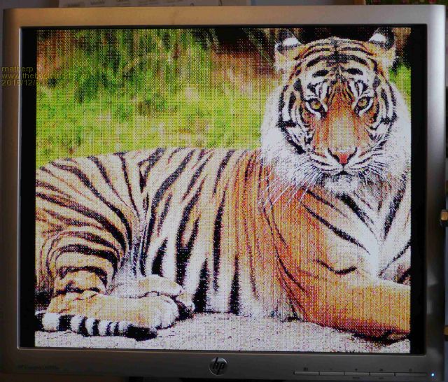 |
||||
| WhiteWizzard Guru Joined: 05/04/2013 Location: United KingdomPosts: 2968 |
Hi Peter, Getting closer to testing. Currently have the 24MHz swapped onto the PCB (i.e. replaced the 12MHz oscillator) and have the Beta successfully loaded and running. About to build the video circuit but can't find any spare diodes so need to pull them from something. Couple of questions: 1> Your comment in the above post about '... lose SPI2 which means no SDcard' only refers to IF you want to use I2C on the 64pinner - correct? I am currently just wanting VGA and SD on kiiids nice little PCB. The SD card does use pin 12 for SD CS so I will alter this to allow VGASync on pin 12. 2> Is there a 'limit' to the length of the VGA. I have a 3m and a 5m one, none shorter unless I pop out and buy one. Do you think a 3m VGA lead between MM and monitor will work ok? Love the 'dithered' Tiger - hope to see it here later on my monitor once I've built the VGA circuit, and sorted an appropriate vga lead. Will update later . . . |
||||
| WhiteWizzard Guru Joined: 05/04/2013 Location: United KingdomPosts: 2968 |
On kiiids PCB, I have cut Pin12 track going to SD CS, and used MM pin 32 as the SD CS. VGA option and SD card working fine together - another step nearer Now to rip out some diodes from something so I can complete the VGA circuit. |
||||
| WhiteWizzard Guru Joined: 05/04/2013 Location: United KingdomPosts: 2968 |
SUCCESS 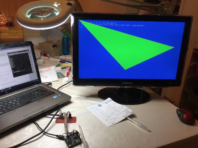 Few things to feedback: 1> I had a loss of the RED signal which I assumed was a loose wire. However, nothing was obviously 'broken' so did a reset and I had the 'RED signal back! Not been able to re-create this, but will keep an eye out for this one. 2> The Triangle command is fantastic. However, can I suggest an extra parameter to match the other command (such as BOX, circle, etc) in that there is a 'line width' parameter.  3> (One for Geoff maybe). I use the OPTION LCDPANEL CONSOLE 1,RGB(...),RGB(...) to set the default colours of the console. Upon a power-up, or a reset, the screen is cleared to black rather than the background colour set in the OPTION LCDPANEL CONSOLE command. Note that any text drawn (such as the welcome message upon power up) is correctly drawn with the foreground/background colours; however, as I mentioned, the rest of the screen is black. The GUI TEST LCDPANEL draws the circles amazingly quick Will keep testing . . . WW |
||||
| WhiteWizzard Guru Joined: 05/04/2013 Location: United KingdomPosts: 2968 |
Peter, If you draw a triangle with lets say a red 'outline' and a green fill and on a black background; then draw another triangle with all the same 'co-ordinates' but this time with a black 'outline' and a black fill, then I would expect the triangle to 'disappear. However, most of the red outline remains on the screen. Have not tried combination of other colours (for outline, fill, or background) but hopefully this is enough information to fix the issue. It was discovered whilst doing a speed test to draw random triangles on the screen; but instead of using CLS to clear the screen, I 'over drew' the triangle in the 'background' colour to make it 'disappear' (but it didn't). Hope this all makes sense . . . . WW EDIT: Using blue outline, green fill, black background also has the same issue, BUT, if changing to Green outline (green fill, black background) then it works as expected  |
||||
| WhiteWizzard Guru Joined: 05/04/2013 Location: United KingdomPosts: 2968 |
Peter, Found a little BUG: concerning 'cropped pixels' I have a console set with white text on blue background i.e. OPTION LCDPANEL CONSOLE 1,RGB(WHITE),RGB(BLUE) Now follow these steps: 1> reset MM (note colour issue reported earlier; i.e.e black screen wherever text is absent - it should be blue) 2> type MEMORY (IN LOWERCASE), and it shows the relevant numbers (note the appearance of the command 'MEMORY' typed above the numbers that appear - it looks ok) 3> hit ENTER a few times to position Command Prompt near centre of screen 4> type MEMORY as before and observe - all is ok 5> now hit enter until lots of times so Command Prompt is on the last line of the screen (no problem if screen scrolls up) 6> now type MEMORY one last time (in lower case) and hit ENTER 7> Now look at the MEMORY command as it was typed and it has cropped the last row of PIXELS WW |
||||
| matherp Guru Joined: 11/12/2012 Location: United KingdomPosts: 11388 |
Pity I didn't see this before I could have made that one line user selectable as part of the OPTION LCDPANEL command. I'll do that anyway in the next release. You will notice that the current LINE command doesn't support the line width parameter for diagonal lines. For the same reason it isn't doable for triangles which are comprised of a set of diagonals. This is an issue Geoff has already picked up on. I'll post a fix in the next beta. I should be able to fix this - I'll have a look This could be your screen not displaying the full 480 lines. My "old" 1280x1024 screen works perfectly - rock solid picture no missing lines. My "good" Dell screen gives a less stable image and the position is one line off. In the next release I will include a fudge factor to allow the vertical position to be adjusted. Try BOX 0,0,640,480 to see if you can see the complete outline Some activities (e.g. writing to flash memory) cause the DMA to loose sync and the SPI channel to lock up. I've tried to trap these but may have missed something. Let me know if you see it again |
||||
| WhiteWizzard Guru Joined: 05/04/2013 Location: United KingdomPosts: 2968 |
Thanks Peter for your response. The 'cropped pixel' issue I think may have been misunderstood. What I observe is the missing pixel row being 'scrolled up' the screen. The lower part of the letter 'y' within the word 'memory' IS displayed when it is typed on the last line of the screen. However, when I hit 'Return' to perform the Memory command (i.e. to display the information) the screen has to scroll up to be able to show the information. When the word 'Memory' is observed (which is now a few lines up from the bottom of the screen), the bottom row of pixels of the letter 'y' is missing. On the note of screen position: I had to adjust the position and size of the whole image on my monitor so that the extremities were visible. Even with the 'auto just' option on my monitor, I still had to manually adjust. I will try more monitors tomorrow to see if this is something that may be of a concern. Will continue to do more testing . . . WW |
||||
CircuitGizmos Guru Joined: 08/09/2011 Location: United StatesPosts: 1427 |
You have an ambitious 'ad' remover.  Micromites and Maximites! - Beginning Maximite |
||||
| WhiteWizzard Guru Joined: 05/04/2013 Location: United KingdomPosts: 2968 |
Nice one CG! I really hate technology that tries to be smart with its spell checking!  |
||||
| matherp Guru Joined: 11/12/2012 Location: United KingdomPosts: 11388 |
OK I understand - found and fixed |
||||
| WhiteWizzard Guru Joined: 05/04/2013 Location: United KingdomPosts: 2968 |
Thats great that you saw it too and were able to fix it. Am going to stop testing now for the night but will continue tomorrow morning. I have to ay this firmware is working really nicely and will gladly test your next release whenever you post it. By the way, are there any other issues that you are aware of with b5v6? Would be good to know; but not to worry if you release a new version to test. WW |
||||
| Grogster Admin Group Joined: 31/12/2012 Location: New ZealandPosts: 9971 |
Any plans to increase the colours to 16 or so, or is that simply not possible? No problems if no. Again, I am just curious. Smoke makes things work. When the smoke gets out, it stops! |
||||
| WhiteWizzard Guru Joined: 05/04/2013 Location: United KingdomPosts: 2968 |
Dare I say it, but I truly believe that the MaxiMite has been reborn Had some simple animation running all night without any issues. I am in & out during the course of today but will continue to test as much as possible as I am really loving this development. |
||||
| Page 1 of 4 |
|||||
| The Back Shed's forum code is written, and hosted, in Australia. | © JAQ Software 2026 |
