
|
|
Forum Index : Microcontroller and PC projects : Simple gas analyser USB problem
| Author | Message | ||||
plover Guru Joined: 18/04/2013 Location: AustraliaPosts: 306 |
I think Forum here is just the right place to get a helping hand to learn about a USB protocol connection problem. Background I bought a small gas analyser based on the MQ-3, multi gas sensor. We have had it for about 10 days. Very simple gas, flows past a heated sensor resistance, a PIC16F1455 i/SL measures the voltage change accross a resistive divider. The result is shown in 'morse code' on green, red, yellow LED. The operator writes the interpreted figure in a book. For those interested in spreadsheets/graphing a PC can be connected via USB port and a program does whatever is needed, etc. In this case a Toshiba Tecra R940 running Win 7 32 bit. After a couple of days getting use to the unit, including calibration and initialisation procedures, we noticed for no reason the message from the program driving the data collection would come up with "device unplugged". It was one of those situations where, connecting cable, sockets, and because it is a very new product the software also fair suspect. Present situation Breakthrough of a sort yesterday, finally the program could no longer connect the unit and Windows declares that device connected unknown. Unit still works in stand alone mode driven by a battery or from the USB power but result must be recorded via 'morse code'. The PIC16F1455 i/SL is physically connected directly via pin 12 and 13. This assumed from visual inspection. I am yet to try and make measurements, I should be able to connect my Oscilloscope when running on the battery. My question what happens when a pic micro (assuming it is programmed properly) is connected to a laptop USB port? Since the laptop does not recognise the device any longer, something that should happen does not? I will see if I can attach a picture of the micro and some tracks. I used Image Upload and it seems to have gone. Yes I can see it in preview. For most of you chaps it is probably self evident how the USB is connected. Though it is an assumption that pin 12 and 13 is used based on few pictures I saw on the internet. 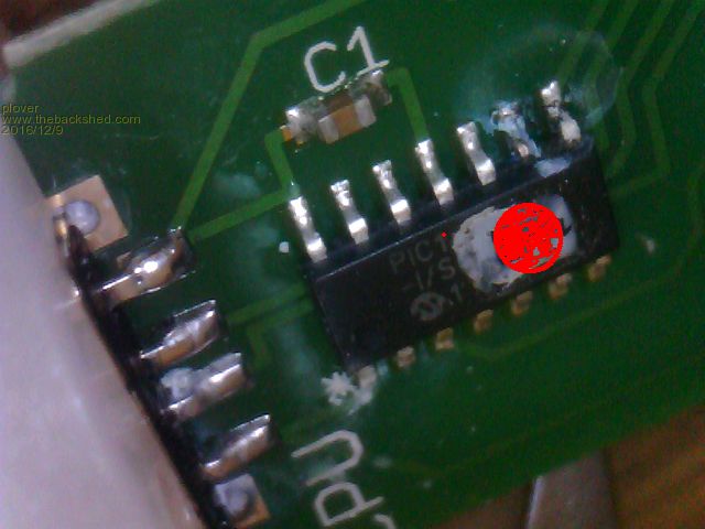 |
||||
| WhiteWizzard Guru Joined: 05/04/2013 Location: United KingdomPosts: 2978 |
As a simple thing to try (if you haven't already), is to swap over the USB lead. I have a box of USB leads here of varying thicknesses. I have some which I know work 100% with anything I plug in such as a PicKit3, logic analyser, data logger, etc. However, some leads will report the 'device unrecognised' or 'there was a problem. . . .' but they sometimes work intermittently. I have found that some leads have very thin cables inside and are not capable of supplying enough power to the device connected. Others are so thin that they have broken internally with possible just a single strand giving an intermittent connection. Bottom line is try a few different leads - not just one (unless it then brings your device back to life!). Earlier today I struggled to program a PIC and MPLAB IPE was reporting all kinds of issues. Turned out it was one of my 'good' leads that had finally failed for whatever reason. I am not saying this is your issue, but like you mentioned, it could be any of a number of things causing this 'failure' you are seeing. Keep us posted . . . |
||||
TassyJim Guru Joined: 07/08/2011 Location: AustraliaPosts: 6533 |
Have you tried "turn it of then back on again" Start with unplugging the pic and removing it's battery to give it a full powerdown reset. The PIC should be sensing the USB power and doing it's initialise routines. I would also try rebooting the PC. The initial disconnects might be the PC putting the USB ports to sleep. Check the power management settings for the USB hubs in device manager. If the software on the PC is running when the connection is lost, it might be like the micromites and the port appears to be present but doesn't work until the program is shutdown and then the device replugged. Bring back serial!!! Jim VK7JH MMedit |
||||
| plover Guru Joined: 18/04/2013 Location: AustraliaPosts: 306 |
Thank you both for replying. Your comments takes me out of going in circles thinking I have tried everything. There is nothing lost going over possibilities again. 1.. The supplied cable is custom made, got a rather nice solid feel to it. I plugged in my USB memory stick and navigated around to various folders and files for a few minutes. Base on this I thought it was ok. Despite this I will try another cable that works, using a normal cable will not look as pretty but it is very easy to do. This begs the question, are there any USB cables generally known that can be trusted to be 'good"? 2.. The device is simplicity itself. There is the PIC chip running without external crystal (if a crystal is there I will be very surprised). There are four tiny LEDs and associated resistors even for surface mount they seem small. A 3 wire cable with connectors goes to the gas sensor mounted on a tiny pcb. One capacitor near the PIC and of course the USB plug. I have just further dismantled the unit and I think that is it. So every time you remove power and apply it again I am assuming that the PIC resets. The beauty about the situation that the unit seems to work fine using the 'morse code' ie communicating the result on coded coloured LEDs At some stage when random unplugging would occur, the problem was fixed simply by turning the program off and on again. The only disadvantage it would send the process into intialisation for approx 5 minutes. You can imagine that starts getting to you when the measurement is normally less than one minute. A few times real intermittent behaviour, the unit would unplug (nicely indicated by clear "plunk" sound from the laptop. Then before getting to laptop it would work again, even without going into initialisation. (loose connection, poor solder joint?) Then gently twisting the plug at either end of the cable would repeat the "plunk". Further interesting Windows would not normally alarm the port as unrecognised. I did think of the laptop power mode settings, I am not crash hot on this but it is set with something like 15 minutes before any attempt of going to sleep. Again it has happened the problem showed up after say 1 hour period, screen blanked and needs waking up by the BlueTooth mouse I am using. 3.. The following point in view of I am running out of mechanical options like poor soldering. I vaguely remember reading about this, I don't really understand. In view of this. it seems that Windows does not necessarily alarm the device as unrecognisable. I mean the analyser program says unplugged, the messages slowly blinks as if retries take place. After a number of those retries Windows may pop up an alarm about the an USB port not recognised. My understanding is that when this hapenns there really is a problem. I wrote I am running out of mechanical options to explain the problem. At a first glance with just a magnifier I noticed discoloration near pin 8 and 9 and even microscope picture almost indicated a clear track hairline. Though that did not make sense because I assumed this was towards the LEDs. Closer inspection after a bit of cleanup shows liberal amount of solder but the crack was a valley in the solder throwing a shadow. I have since scraped the 'grey stuff' perhaps hotmelt something off the chip enough to just about decipher the pic16F1455-I/S(L?). 4.. A bit more work to be done on the mechanical side, like checking continuity on the USB D+/D- from the plug to the IC but it looks proper. My thinking is what can I expect on the D+/D- on a proper running connection between a laptop port and a "device". Should D lines be pulled down or pulled up to signal connection etc. I should mention I can partly monitor USB traffic/messages on the port USB ports with Wireshark but again I don't know what messages goes back and forth when connecting the device, just when I was ready it crashed completely. Took some time to get a form of Wireshark running and when I understood the operation of Wireshark it was too late so far.  Added later: Can now confirm that USB D+/D- have continuity to the pic pins 12 and 13. Tested another cable, same result as proprietary cable, USB port not responding For the linux minded, plugged unit in and tested lsusb in a terminal, no port connection (I feel a bit more comfortable in Linux) Have downloaded the pic16F145X Data Sheet (418 pages food for the weekend) and flipped to section 26 USB, interesting stuff here which I can follow in theory but in practice I am stuffed at the moment. Did figure out that USB can be configured on pin 12 and 13. (Of course makes sense as the device have worked for over a week many hours a day, minor outages on and off until permanent crash)There is also something about termination resistors need to be programmed in, but exactly how this can be tested in practice is not clear. Assuming USB programming is done and the device is powered on only, D+/D- not connected what voltage level can be expected. Looks like a good time for making a USB breakout box too. |
||||
| plover Guru Joined: 18/04/2013 Location: AustraliaPosts: 306 |
I should mention that we are under the 30 day warranty money back or replacement guarentee. However as soon as I saw the unit I figured out what might be inside and was very keen to have look. Contacted supplier and asked if it was ok to look at the problem given my eletronics background. I did not expect this would happen but was very pleasantly surprised by permission and arrangement to return it later would be done. The opportunity to investigate simply too irresistible. Incentive to learn a bit about USB operation. My quick read of the manual also reveal something about the USB protocol structure such things as: Isochronous, Bulk, Interrupt and Control this was words I saw when applying Wireshark analyser to the USB ports on the laptop. Since the PC's do not seem to know there is a new device, this is not of much help at the moment. Inspiration struck (a bit late) I have a fully built Maximite Colour system, I was reminded here in forum that these of course come with USB connection. At this stage it is all I want to know. Promptly finding a USB cable -A-B and plugin into Linux and doing: "dmesg |grep usb" .............................. [ 0.000000] usb 5-1: New USB device found, idVendor=04d8, idProduct=fd52 [ 0.000000] usb 5-1: New USB device strings: Mfr=1, Product=2, SerialNumber=0 [ 0.000000] usb 5-1: Product: Maximite [ 0.000000] usb 5-1: Manufacturer: Silicon Chip [ 0.000000] usb 5-1: USB disconnect, device number 2 [ 0.000000] usb 5-1: new full-speed USB device number 3 using uhci_hcd [ 0.000000] usb 5-1: New USB device found, idVendor=04d8, idProduct=fd52 [ 0.000000] usb 5-1: New USB device strings: Mfr=1, Product=2, SerialNumber=0 [ 0.000000] usb 5-1: Product: Maximite [ 0.000000] usb 5-1: Manufacturer: Silicon Chip [gert@kde64byTexstar ~]$ Even better I hav Wireshark running here on Linux too: 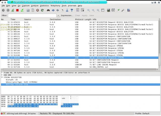 I was looking for something like that, I consider the Maximite similar to the gas analyser in this initial phase of setting up. Maximite gave me swag of commands from the USB protocol, these are a bit heavy duty to decipher but the gist of operation can be had. In this case I also had the filtered USB output from dmesg in Linux so in my mind that pretty well nails it. If the analyser PIC 16F1455 -I/SL was working properly I should have seen something similar. This I can take back to the manufacurer. Summing up: Mechanically up to pin 12 and 13 the analyser seems sound, USB connected to this 'port' and the PIC seems to work messaging via the LEDs. Appears USB protocol no longer working or configured correctly. I am making up a USB breakout board so I can measure easier on the D+/D- lines, both DC levels and see if I can get some screen cuts on my Oscilloscope. (Not sure if it can decode USB, that would be fun) Question: Is it possible to interrogate this micro with a pickit 3 or something. Happen to have such a kit in it wrappings still? |
||||
| plover Guru Joined: 18/04/2013 Location: AustraliaPosts: 306 |
Making this simple breakout device seemed to take for ever, finding the parts and then decide. Soldering also took more than just 5 minutes. I spent a lot of time making sure the connections were right. Especially the power supply not getting interchanged. That did not happen fortunately. When using the break out the power went nicely to the MaxiMite. Looking for enumeration, well that did not happen. Went over the D+/D- lines and there was a problem with my soldering as the line resistance was about 7 Mohm. Another half hour went by to get this cleared up. Another try still no enumeration I was starting to feel it was uphill work. Finally I discovered the the USB B connector may be problematic, seems it would supply the power just fine but the D lines or one of them did not come up to scratch. I pushed on the connector and imagined I felt it move in a fraction. Whatever it was it came good. Maximite enumerates and I get comment by using linux: dmesg | tail -30 Above show the last 30 lines of dmesg but you have the action this whenever you want a new set of data. [code]tail -f /var/log/messages[/code] Above is better, messages just rolls past as the messages comes in. A bit more convenient when repeated connect/disconnect caried out. DC measurement When the Maximite is plugged into a USB port and just sitting idle. D+= 0.0V and D-=3.0V when nothing plugged into the port the voltage from the PC on the D lines is both 0V. When I plug my gas analyser in to the same port the expected 3.0V on the D- line does not show. A varying floating DC voltage, from minimum about 200 mV to a maximum of 900 mV. Wonder if it is the attempt to get up to 3.0V, like a pull down resistor missing (if such is needed). Too late tonight, I will read a bit about the USB port configuration and implementation before trying any more experiments. |
||||
| JTR0701 Regular Member Joined: 10/07/2013 Location: AustraliaPosts: 71 |
I would start by adding a 1uf - 4.7uF capacitor across pins 1&2 of the pic. It is not right that there is (apparently) no cap here. It is pretty much standard that the Vdd rails must be bypassed. Edit: by the sounds of it the pic may well have scrambled its own firmware, possibly due to the noisy rails. Can't say for certain but it is one possibility... |
||||
| plover Guru Joined: 18/04/2013 Location: AustraliaPosts: 306 |
I Assume you mean power supply decoupling, pin 1 is GND and pin 14 is +5V, pin 2 is RA5 on this PIC. There is no power decoupling and I agree it would not hurt but I have no idea if it is required. Remember it appears to work fine but for the USB port gone on strike slowly. Good point about software and it is pointing towards a reload may be only chance. Later in the day I hope to get the oscilloscope connected. I have just looked up the USB section in the Maximite PIC32MX795F512L-80I/PF data and looked at the circuit diagram. This has a 1 K resistor ins eries with the USB v+ pin, wondering about the purpose for this. I was more interested in the D+/D- lines but they are direct connected as on the PIC16F1455. |
||||
| JTR0701 Regular Member Joined: 10/07/2013 Location: AustraliaPosts: 71 |
You might want to check that again. It's not right. Pin-14 is Ground. |
||||
| plover Guru Joined: 18/04/2013 Location: AustraliaPosts: 306 |
JTR0701 You are quite correct, I made a mistake, I 'wanted' pin14 to be posive supply some years ago all integrated logic had that corner pin as plus, well most. You have probably saved me blowing up the circuit if I was going to apply power with flying leads, much appreciated. Even I wondered about the C3 capacitor I should have followed up on that as I thought it ought to have gone to GND well now it does.  |
||||
| isochronic Guru Joined: 21/01/2012 Location: AustraliaPosts: 689 |
don't know if this helps but I get very similar symptoms when I am using a battery powered usb-connected pic and the battery voltage tanks..pic works ok but usb gets exasperating..after power is healthy again all is ok |
||||
| plover Guru Joined: 18/04/2013 Location: AustraliaPosts: 306 |
chronic Well that is interesting. Can you give any figures for voltage levels when trouble starts? I had better get back into the analyser again and measure voltages on the pins of the micro. Will look with oscilloscope at the same time to see if I have noise levels as well. |
||||
| isochronic Guru Joined: 21/01/2012 Location: AustraliaPosts: 689 |
not really, (just the regulator input was too low for it to function). The sensor is probably drawing a fair current while it heats, maybe that is hitting the USB power, ground etc |
||||
| plover Guru Joined: 18/04/2013 Location: AustraliaPosts: 306 |
This problem got more and more odd until it finally started to fall into place. When I got the oscilloscope on the breakout board I had made up for the USB. The power never played up or I have not noticed. Looking at the USB D+/D- lines, there was odd behaviour, could not get consistent results repeating the same test. When I found out that two USB cables I use regularly would fail on the analyser that was the turning point. I started moving the cable connection about carefully making sure powered never flinched but the oscilloscope on the D lines started misbehaving, it was apparent that the D- line was not making contact, tempted to say it was arching. Turns out that the custom supplied cable, plus two of my cables when pushed on to the plug socket fully home would fail but if withdrawn approx 1 mm they will work. Another shorter USB cable I have did not have that problem. The Analyser has been used for several hours and working fine, just a few minutes ago "device disconnected" showed and was easily fixed my slightly pulling back on the cable. It is hardly worth the trouble replacing the plug at this stage, seems easier to insert a small gasket like cardboard piece preventing pushing too far. I will go back to the supplier and suggest they send me two new plugs tested to work. I tried to use my USB micro scope to look inside the plug but I do not have good field of depth. I did think I could see something that looked like corrosion on the D- contact but really not conclusive, even a cleaning attempt did not change the picture a lot. It took me an inordinate amount of time but I am satisfied that I now what the problem is. Part of the time I can write off as a crash course in USB port design and operation. I even managed towrk out from the D+/D- line operation that the analyser was running a USB 1.1 or fullspeed later confirmed when I could see the enumeration when connecting to my linux system. chronic Well in a way it seems you were right a bit less voltage and noise on a line and I was in deep trouble.  Post Script: After a couple of times giving "device unplugged" I got the micro scope out diligently took some more photos from inside the plug as best I could. It seemed there was somthing like corrosion on the D- finger. I tried to carefully scrape with a small scalpel, toothpick was not effective. The finger appeared cleared of what ever it was. For the moment it seems to be working fine, no need to pull connector back 1 mm or so to keep it working. This is a weird problem. For my record, above still did not last more than a couple of days. Inspection of the male USB plug does not seem to reveal the problem. So the last try is bypassing the USB plug by soldering in 4 wires connected to a plug and breakout board if oscilloscope measurements needed. A tedious delicate job to try and solder in the wires with shaky hands. Got them in place and the operation seems much more robust. I must get a couple of USB A surface mount male plugs and replace the existing one. |
||||
| The Back Shed's forum code is written, and hosted, in Australia. | © JAQ Software 2026 |
