Notice. New forum software under development. It's going to miss a few functions and look a bit ugly for a while, but I'm working on it full time now as the old forum was too unstable. Couple days, all good. If you notice any issues, please contact me.
isochronic Guru Joined: 21/01/2012 Location: AustraliaPosts: 689
Posted: 04:23pm 26 Dec 2016
Copy link to clipboard
Print this post
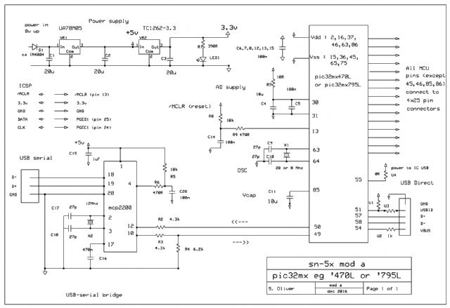
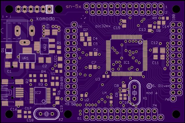
This is a small pcb for 100 pin /14mm pic32mx, it should be ok for pic24 and dsPic also. It might be described as a self-powered mcu board with pin connectors and usb and serial-usb ports. Practically all the mcu pins are brought out to the connectors. The regulator gets a little hot at 12 v but is ok for moderate currents. The power supply is under-designed, I had some surplus 20uF tantalum caps so I used those, most components are not critical. It is tested and works OK.
It was originally intended only as an exercise but turned out to be too useful in its own right. This is mod a which is almost certainly the final version as I have moved on to the MZ version sn-7x. Others have requested it, I promised schematics etc so here it is.
Please refer to it as "sn-5x", any errors please tell me !
schematic :
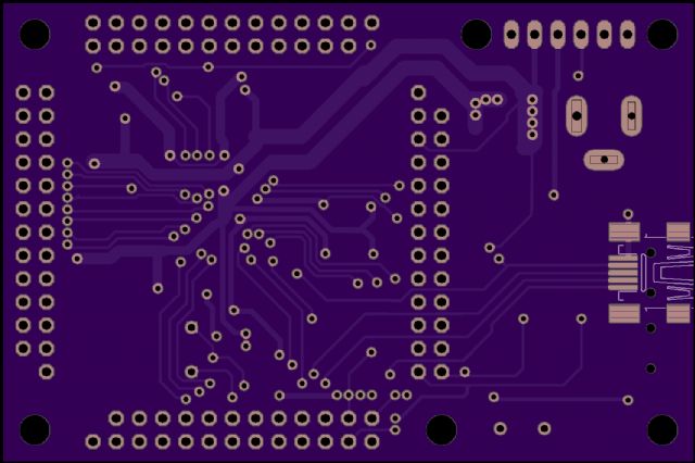
the pcb :
and components :
Component list for sn-5x
-Power supply D1 Diode 1A uncritical D0214AC C1 Cap 20 uF uncritical 3528 VR1 Regr 5V uncritical SO-223 C2 Cap 20 uF uncritical 3528 VR2 Regr 3.3v eg Microchip TC1262-3.3 SO-223 C3 Cap 20 uF uncritical 3528 LED1 Led Green uncritical 1206 R1 Res 330 Ohm uncritical 0805/0603
-MCU C5 Cap 0.1 uF ceramic bypass 0805 C6 Cap 0.1 uF ceramic bypass 0805 C7 Cap 0.1 uF ceramic bypass 0805 C8 Cap 0.1 uF ceramic bypass 0805 C11 Cap 10 uF (critical) ceramic 1206 Murata C12 Cap 0.1 uF ceramic bypass 0805 (oversize pads on pcb) C14 Cap 0.1 uF for /MCLR 0805 C15 Cap 0.1 uF ceramic bypass 0805 R7 Link 0 Ohm initial link for A/D supply R8 Res 10 K for /MCLR 0603 R9 Res 470 Ohm for /MCLR 0603 IC1 IC pic32MX470 100 pin /14mm
-Serial via USB comms C16 Cap 470 nF IC reg 0805 C17 Cap 22 pf Crystal 0603 C18 Cap 22 pF Crystal 0603 C19 Cap 1.0 uF ceramic 0805 C20 Cap 0.1 uF IC2 /MCLR 0805 R2 Res 6.2 K serial protect 0603 R3 Res 4.3 K serial divider 0603 R4 Res 6.2 K serial divider 0603 R5 Res 10 K IC2 /MCLR 0603 R6 Res 470 Ohm IC2 /MCLR 0603 X2 Crystal 12MHz IC2 IC MCP2200
-Assorted hardware 1 Barrel socket for powerlead 1 pin header, 6 pin, for ICSP/pickit3 4 25-pin sockets or pin headers (use dual-row 13 pin, remove a pin) 2 USB mini-B smd connectors Insulating pad for crystal (or just leave it elevated)
-Optionals-
[ For A/D measurements ] R7 Res 10 Ohm AD supply (replaces link) 0603 C4 Cap 10 uF AD supply filter 0805
[ Crystal for timing ] X1 Crystal eg 20 MHz C9 Cap 22 pF Crystal 0603 C10 Cap 22 pF Crystal 0603
[ Direct USB ] U1 Res 100 K Pullup (not required?) 0603 U2 Res 1 K USB power sense 0603 U3 Res 0 Ohm Link to connect USBID line U4 Res 0 Ohm Link, supplies 3.3v to mcu usb
Edited by chronic 2016-12-28
isochronic Guru Joined: 21/01/2012 Location: AustraliaPosts: 689
Posted: 03:30pm 27 Dec 2016
Copy link to clipboard
Print this post
I should add, the serial comms use pins 49 and 50, but there is provision for rerouting, ie flying leads can connect the bridge to any other two pins, and the connections to 49 and 50 have a cut zone and so can be severed cleanly if needed - it is a fairly generic board. As a hardware test I loaded the explore100 micromite software on it and the chevron prompt popped up OK on the USB console. If a serial connection via 87/89 is needed it may be ok to simply connect 49/50 to 87/89 as well, I am not sure how MM/explore100 uses 49 and 50. Pin 49 is described as usbid, 50 a 1Hz clock, so they are probably read inputs, is that right ?