
|
|
Forum Index : Microcontroller and PC projects : HC-12 RF module antenna.....
| Author | Message | ||||
Grogster Admin Group Joined: 31/12/2012 Location: New ZealandPosts: 9063 |
Hi folks.  The HC-12 RF module like this one here: 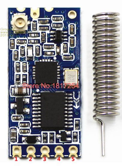 ...they come with little helicals so they are ready to use right out of the box, but does anyone know what frequency these antennas are wound for? Usually, you can't have a frequency deviation of more then about 5MHz from what the helical is wound for, or the match will be horrible and you won't get the best performance from them. In NZ, you are allowed -10dBW(100mW) in the 470MHZ SRD band, so I want to set the HC-12's for that frequency and run them full-power, but my concern is that the helicals will now be about 40MHz out, and the match will be terrible, subsequently the performance(read: range) will not be as good as it could be I would prefer to use the 470MHz band, as not many things use it here, whereas the 433MHz band is quite active. IF they are most likely 433MHz helicals, perhaps I can just cut a few turns off the top of them to tune them more to the 470MHz band? As I am moving up in frequency, cutting the antenna to match becomes a possibility. You can't do that if you need to cut it longer.  Comments? Smoke makes things work. When the smoke gets out, it stops! |
||||
| hitsware Guru Joined: 23/11/2012 Location: United StatesPosts: 535 |
No documentation addressing your concerns ? |
||||
| Phil23 Guru Joined: 27/03/2016 Location: AustraliaPosts: 1664 |
I'm definitely not a radio guy Grog, but would this help at all? Looks like 19 turns in your pic. haven't counted the ones I have here, but can do that & probably work out the unwound length of the wire. Seems like stretching the coils would increase the gain; maybe? Cheers. Edit:- Maybe someone like TassyJim can add some light to a few things? IE is this uncoiled length of the helix a fraction for the wavelength? 433MHz=693mm. Is the length simply related to that? Without taking any real measurements, I guess it's about 300mm stretched out. |
||||
| srnet Senior Member Joined: 08/08/2014 Location: United KingdomPosts: 164 |
Well there is the theory and the reality. I am a strong beliver in checking for the reality, so I would set up one of the HS12s for the required frequency and measure the signal strength at a set distance, say 50M. Then cut a 1/2 turn off and measure again, etc. Cannot see how else you will know for sure what is the actual best length. $50SAT is Silent but probably still working. For information on LoRa visit http://www.loratracker.uk/ |
||||
lew247 Guru Joined: 23/12/2015 Location: United KingdomPosts: 1676 |
The best option is don't use the helical coil at all use a 1/4 wavelength piece of straight wire for the antenna At 433 Mhz this is appx 16.7cms in length To find the optimum length for the wire its 300/frequency divided by 4 to give you the length then multiply by 0.95 to allow for the velocity factor of the wire used. 0.95 is a best guess, if you want to be exact google the velocity factor of the type of wire used - but in reality 0.95 is a good guess Therefore just under 17cms for the piece of wire EDIT: 470Mhz the length of wire is 15.15CM btw the wire can be vertical or horizontal - just don't coil it |
||||
| srnet Senior Member Joined: 08/08/2014 Location: United KingdomPosts: 164 |
There is no way a calculator will tell you the best length for the antenna on this type of module. These modules do not use precision matching components between the RF IC and the antenna connection, so its anybodies guess what the exact output imepedance is and this will of course affect the antenna length. My experience of a great deal of testing of a similar module to the HC12, the RFM22B, is that the RF output could vary a great deal, by as much as 10db, if you insist on using a calculator to work out the antenna length. If you want to peak output you really do have to tune the antenna to suit the module. For a 1/4 wire and a less than perfect groundplane, I would start out at around twice the calculated length and trim downwards. For a balanced dipole, possibly at 1.5 times the calculated length and then trim downwards. $50SAT is Silent but probably still working. For information on LoRa visit http://www.loratracker.uk/ |
||||
| hitsware Guru Joined: 23/11/2012 Location: United StatesPosts: 535 |
How does one measure the output ? |
||||
| srnet Senior Member Joined: 08/08/2014 Location: United KingdomPosts: 164 |
You need a receiver that will report the signal strength. There are handheld devices thay will do the job very well, such as; http://j3.rf-explorer.com/ An RTL USB dongle (around Ł6) connected to a laptop will do a very good job of measuring signal strength as well. Granted it takes a bit of time and effort to do a proper job of optimising a TX antenna, which may be why its assumed a calculator and a bit of theory has all the answers. $50SAT is Silent but probably still working. For information on LoRa visit http://www.loratracker.uk/ |
||||
| Phil23 Guru Joined: 27/03/2016 Location: AustraliaPosts: 1664 |
The Ideal tool is an RF spectrum analyser, but an expensive instrument, many $1000's. The next closest thing I've played with several years back was an SDR. Software Defined Radio. A few years back I played around with SDR using a Realtek RTL2832U DVB-T Tuner Dongle. $15 from ebay. Covers a frequency range of 24 – 1766 MHz. 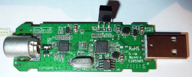 Just a matter of plugging it in & installing the software. Silicon Chip had an article back in May 2013. You can get outputs like this, 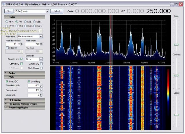 That are really helpful for seeing signal strengths of devices, an to also see what else is about on nearby frequencies that could be interfering with each other. For the $15.00 it's a worthwhile tool to have. Good resources in this site. Phil. |
||||
| Phil23 Guru Joined: 27/03/2016 Location: AustraliaPosts: 1664 |
Lol, Beat me to it by 1 minute. But I reckon I bet bonus points for the pics. Edit:- RF Explorer looks like a neat little device.... |
||||
palcal Guru Joined: 12/10/2011 Location: AustraliaPosts: 1802 |
Grogs, Silicon Chip had an article a few years back on WiFi antennas, I think they described a bowtie arrangement. Paul. Edit. Come to think about it, it may have been 2.4Ghz I will see if I can find the article. "It is better to be ignorant and ask a stupid question than to be plain Stupid and not ask at all" |
||||
| Grogster Admin Group Joined: 31/12/2012 Location: New ZealandPosts: 9063 |
Thanks everyone, for your comments - appreciated. I will have a bit more of a play, and try some bigger antennas on them via the U.FL sockets and see if that helps. They are a great wee module and work very well for the price! Smoke makes things work. When the smoke gets out, it stops! |
||||
| srnet Senior Member Joined: 08/08/2014 Location: United KingdomPosts: 164 |
It sure makes tuning antennas a breeze, and for what it does its not expensive. You can make a single frequency signal strength meter quite easily with a a RFM22B, just have it constantly reading the RSSI register and print it out to a display. $50SAT is Silent but probably still working. For information on LoRa visit http://www.loratracker.uk/ |
||||
| Phil23 Guru Joined: 27/03/2016 Location: AustraliaPosts: 1664 |
So I went & dug the USB tuner up a few minutes ago & plugged it into my laptop. 2 minute exercise to install the drivers & software. This is what I'm seeing from my HC-12's using the approximately 4" whip antenna supplied. 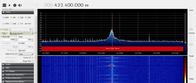 That spike is the master polling the slaves; (master under a metre from me) I can just see the slaves respond; (about 8m away). As they are interrupt driven, their response is almost instantaneous, so easily lost on the spectrometer. Could easily address that by giving them a 200ms pause for testing purposes. It does peak a bit higher than seen above, just hard to get a screen capture. Maybe for testing purposes a bit of code to continuously send data would be the go. Phil. |
||||
