
|
|
Forum Index : Microcontroller and PC projects : Gel-Cell charger?
| Author | Message | ||||
Grogster Admin Group Joined: 31/12/2012 Location: New ZealandPosts: 9588 |
Hi - does anyone have any part numbers for a Gel-Cell charger, or perhaps just a simple circuit? I need a fully automatic one that switches to battery if the mains fails, and back to charging when the mains returns, all without ever disconnecting the 12v supply to the equipment. At the moment, I do this with a diode gate and a charging resistor, the latter of which is chosen depending on the charge rate you want and the battery you are using:  This circuit being simplicity itself, in that the resistor sets the charge rate of the battery, and the diode gate blocks the battery going back down to the PSU if the mains fails, and bypasses the charging resistor to supply the circuit in the same situation. This circuit is for float-charging Gel-Cell's ONLY. I never use it with NiMH or Li-ION or anything like that! This works, and I have no problem using it, but I am wondering if there is a better way or more efficient way. Happy to look at charging IC's or other circuits BUT whatever people come up with, it HAS to be fully-automatic like this design is. A Gel-Cell stand-alone charger is NOT suitable, as the battery remains connected permanently, and must take over if the mains fails, not be taken out to charge it. I'm primarily looking for a design that will stop charging when the battery is full, or can signal the MM or similar controller if it thinks the battery is bad etc. Open to any suggestions, links, IC part numbers, schematics etc. I like the current circuit, cos it is so simple and it does work just fine. You do lose 0.6v across the diode, and that gets worse if you are sucking a large current, but that could be easily enough changed so that MOSFET's were used there instead of diodes. I have seen this design used in a few different places around the net and they tend to use a 12v lightbulb as the charge current limiter, the benefit of which is that if the battery tries to suck too much current on charge, the bulb lights up and can be used to indicate a charging fault. Smoke makes things work. When the smoke gets out, it stops! |
||||
| Phil23 Guru Joined: 27/03/2016 Location: AustraliaPosts: 1667 |
Don't suppose you could use one of these then? 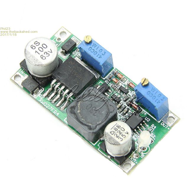 Along with either your existing circuit or a DPDT relay? |
||||
| greybeard Senior Member Joined: 04/01/2010 Location: AustraliaPosts: 172 |
Depends upon how much power is involved in this setup. Existing cct seems to cover most requirements. Stick a couple of resistors across the input supply and battery and feed them into a/d inputs to determine if mains is on, battery charging, charge rate etc. As battery charges the current will decrease anyway as the voltage drop across the charging resistor reduces. You could use schottky diodes if volt drop is an issue and like you say you could also use FETS if needed. Apart from the entertainment value in making it more complicated, if it works and is simple and cheap, why bother fixing it with complications? |
||||
OA47 Guru Joined: 11/04/2012 Location: AustraliaPosts: 982 |
Grogs, I recently had to set up a standby SLA battery on a radio concentrator. For simplicity I used the off the shelf Jaycar SLA charger across the 12 Volt battery. This seems to working OK if your supply current is under 1A the MB3619 will probably do. The Link to the one I used |
||||
| Grogster Admin Group Joined: 31/12/2012 Location: New ZealandPosts: 9588 |
You make an excellent point. I am happy with it the way it is, but I pop this thread out there, in case others have an even better idea.  @ Phil23 - interesting little module. Smoke makes things work. When the smoke gets out, it stops! |
||||
| robert.rozee Guru Joined: 31/12/2012 Location: New ZealandPosts: 2428 |
one small addition you may like to consider is adding a precision zener diode across the gel cell. the ideal regime for charging lead acid batteries is constant current/constant voltage (much the same as with Li-Ion), with the voltage cutoff set to either 13.4 or 13.8 volts, dependant upon the battery. note that the effects of over-voltage with lead acid batteries is gradual degradation, as opposed to with Li-Ion where the degradation can be rapid and 'explosive'. in many installations using lead-acid batteries the degradation may be negligable compared to the battery service life. something like a TL431 can be used to limit the voltage, with an added pass transistor if needsbe. if constant power dissipation is a concern you can add a (relay controlled) charge current boost that is activated after any significant power outage. cheers, rob :-) |
||||
palcal Guru Joined: 12/10/2011 Location: AustraliaPosts: 1982 |
I think Grogs mention of the light bulb was more an attempt at constant current than an indicator. As the current increases so does the resistance of the lamp thus affording some sort of regulation. Paul. "It is better to be ignorant and ask a stupid question than to be plain Stupid and not ask at all" |
||||
| lizby Guru Joined: 17/05/2016 Location: United StatesPosts: 3349 |
So, for instance (with an ASCII art diagram)? [code] e.g., 12V wallwart-o------->|-------o-----Load | schottky | POWER .-. 1N5820 3A | | | ?R - schottky | | ^ 1N5820 3A '-' | | | o----------------' | 12V Battery (GEL Cell) | | 0V [/code] Battery backup 12V trickle-charged: schottky 1N5820 3A or 1N5817 1A What value of R is appropriate? PicoMite, Armmite F4, SensorKits, MMBasic Hardware, Games, etc. on fruitoftheshed |
||||
| palcal Guru Joined: 12/10/2011 Location: AustraliaPosts: 1982 |
Depends on the battery I suppose, I would start with about 12 ohms and measure the charging current, then adjust by trial and error. Paul. "It is better to be ignorant and ask a stupid question than to be plain Stupid and not ask at all" |
||||
| Grogster Admin Group Joined: 31/12/2012 Location: New ZealandPosts: 9588 |
You really need that extra diode in-line with the wallwart, NOT after the battery as you have your ASCII drawing - see my one at top of this thread. The purpose of that diode, is to prevent the Gel-Cell battery trying to send juice into the OUTPUT of the wallwart if the mains is disconnected - never a good thing, and depending on the design of the wallwart, could be catastrophic for it's output if the input is disconnected. Paul is exactly right - it very much depends on the battery you elect to use. In my case, I aimed for ABOUT a 50mA or so trickle, so I ended up with 18 ohms for my 12v/3Ah Gell-Cell, and that seems to work fine. I just used a 1W carbon resistor, mounted proud of the PCB for cooling. It does not get very hot anyway. Smoke makes things work. When the smoke gets out, it stops! |
||||
| palcal Guru Joined: 12/10/2011 Location: AustraliaPosts: 1982 |
I don't know what input voltage Grogster is using but ideally it should be the battery standby voltage plus the drop across the diode. If only 12v. the battery will never fully charge and it's life will be shortened. I don't know what an unregulated 12v wallwart would output, I have measured them unloaded and they are much higher than 12v. I personally have a 12v Gel Cell I need to keep charged and I use a 12 watt solar panel and a regulator like THIS one. Paul. Edit: Wallwart?? I wish the Yanks would call them Plugpacks  "It is better to be ignorant and ask a stupid question than to be plain Stupid and not ask at all" |
||||
| Grogster Admin Group Joined: 31/12/2012 Location: New ZealandPosts: 9588 |
LOL!!!! Yeah, me too!  Yes, my input voltage is fully adjustable, so I setup the input voltage so that the voltage at the BATTERY is 13.8v. This means the actual input voltage is about 14.4v, cos we drop 0.6v or so across the diode. I use a 6A diode, which has good figures for that drop, even under load. Smaller diodes, when you load them up, that 0.6v figure tends to get worse, so using a diode which is overkill means it never gets loaded up that much, so the drop across it is a bit more predictable across all loads it is going to see flowing through it. Smoke makes things work. When the smoke gets out, it stops! |
||||
| Paul_L Guru Joined: 03/03/2016 Location: United StatesPosts: 769 |
Plugpacks??? Wallwart??? OK, that computes. As long as you Aussies and Kiwis don't start trying to explain Cricket to us Yanks we'll be OK. Paul in NY |
||||
| lizby Guru Joined: 17/05/2016 Location: United StatesPosts: 3349 |
Sorry for the transcription error with the diode. So, perhaps [code] power pack, e.g., 18V--DC-DC--->|----o----------------o-----Load schottky | | POWER 1N5820 3A .-. | | | 18R 1W - schottky | | ^ 1N5820 3A '-' | | | o----------------' | 12V Battery (GEL Cell) | | 0V Battery backup 12V trickle-charged: schottky 1N5820 3A or 1N5817 1A or MBR745 7.5A experiment to determine proper voltage for charging [/code] Do you use something like a laptop charger for your power pack? Then perhaps for DC-DC, something like this (3A)? http://www.ebay.com/itm/DC-DC-Step-Down-Power-Supply-Adjustable-Module-With-LCD-Display-Without-Case/272241993041 Would this be a suitable Schottky diode (45V, 7.5A) http://www.jameco.com/Jameco/Products/ProdDS/790954.pdf And one "proud" 18 ohm 1W resistor (for 12v/3Ah Gel-Cell). PicoMite, Armmite F4, SensorKits, MMBasic Hardware, Games, etc. on fruitoftheshed |
||||
| Grogster Admin Group Joined: 31/12/2012 Location: New ZealandPosts: 9588 |
My raw PSU is a step-down transformer, feeding my own PSU board. That outputs about 14.4v(at the regulator output, before the diode-gate):  The FanSink is a Video-card chip-set cooler, and the main 350 regulator and 7809 for the cooling fan are mounted horizontally underneath, and attach to the FanSink bottom via a hole cut in the middle of the board. There is a big barrier-strip(screw terminal) output block, and also an 8-way power+sensor output, which can connect to the MM's I use, and they can then monitor the PSU vitals such as FanSink temp, FanSink fan tacho and charging resistor temp etc, and monitor the fuse and mains for failures. EDIT: I should also mention that there is a insulating gasket under the fansink, the same shape as the fansink footprint, to both isolate the tabs of the regulators, allow heat transfer, and prevent the fansink from touching the top tracks running under it. I used blue 0.5mm thick thermal pads from eBay, and just cut them to match the fansink by running a knife around the edge of the fansink to get the gasket shape. Smoke makes things work. When the smoke gets out, it stops! |
||||
| The Back Shed's forum code is written, and hosted, in Australia. | © JAQ Software 2025 |
