
|
|
Forum Index : Microcontroller and PC projects : automatic clock trim for MX170
| Author | Message | ||||
| robert.rozee Guru Joined: 31/12/2012 Location: New ZealandPosts: 2542 |
for quite a while i've been thinking about automatic trimming (disciplining) of the cpu clock on an MX170 micromite using an external crystal reference. this might take the form of the 1Hz output from an RTC module, or be derived from the 50/60Hz mains, or (in my case) obtained from a 32kHz watch crystal attached to a CD4060 ripple counter that generates a 2Hz output. the big advantage of this approach, over simply using periodic calls to RTC GETTIME, is that frequency measurement, PWM, and other cpu clock dependant functions are also trimmed. with the 2Hz signal from my CD4060 hooked up to pin 26, i used the following piece of code, implementing a crude proportional�integral control loop: SetPin 26, inth, trimISR Do Print count, Str$(E,3,2), Str$(I,3,2),, trim, Time$, Timer Do: Loop Until flag flag = 0 ' comment out this line to consume computrons Loop trimISR: count = Timer Mod 500 E = 250 - count I = ((I * 0.8) + (E * 0.2)) trim = Fix((E * 0.3) + (I * 0.7)) If trim < -31 Then trim = -31 If trim > 31 Then trim = 31 Option clocktrim trim flag = 1 IReturn thr results were surprisingly good, with extremely quick convergence to a stable state, although the loop stabalized at values around 256 (in my case) rather than the target of 250. this doesn't really matter, as long as it is stable: > run 0 0.00 0.00 0 00:00:15 15186 361 -111.00 -22.20 -31 00:00:15 15369 355 -105.00 -38.76 -31 00:00:15 15863 349 -99.00 -50.81 -31 00:00:16 16357 344 -94.00 -59.45 -31 00:00:16 16851 338 -88.00 -65.16 -31 00:00:17 17345 332 -82.00 -68.53 -31 00:00:17 17839 326 -76.00 -70.02 -31 00:00:18 18334 320 -70.00 -70.02 -31 00:00:18 18828 314 -64.00 -68.81 -31 00:00:19 19322 309 -59.00 -66.85 -31 00:00:19 19816 303 -53.00 -64.08 -31 00:00:20 20310 297 -47.00 -60.66 -31 00:00:20 20804 291 -41.00 -56.73 -31 00:00:21 21298 285 -35.00 -52.39 -31 00:00:21 21793 279 -29.00 -47.71 -31 00:00:22 22287 273 -23.00 -42.77 -31 00:00:22 22781 268 -18.00 -37.81 -31 00:00:23 23275 262 -12.00 -32.65 -26 00:00:23 23769 257 -7.00 -27.52 -21 00:00:24 24264 253 -3.00 -22.62 -16 00:00:24 24761 251 -1.00 -18.29 -13 00:00:25 25258 249 1.00 -14.43 -9 00:00:25 25756 248 2.00 -11.15 -7 00:00:26 26256 248 2.00 -8.52 -5 00:00:26 26755 248 2.00 -6.41 -3 00:00:27 27255 249 1.00 -4.93 -3 00:00:27 27756 249 1.00 -3.75 -2 00:00:28 28256 250 0.00 -3.00 -2 00:00:28 28757 251 -1.00 -2.60 -2 00:00:29 29258 252 -2.00 -2.48 -2 00:00:29 29759 252 -2.00 -2.38 -2 00:00:30 30260 253 -3.00 -2.51 -2 00:00:30 30760 254 -4.00 -2.80 -3 00:00:31 31261 255 -5.00 -3.24 -3 00:00:31 31762 255 -5.00 -3.59 -4 00:00:32 32262 256 -6.00 -4.08 -4 00:00:32 32763 256 -6.00 -4.46 -4 00:00:33 33263 256 -6.00 -4.77 -5 00:00:33 33763 256 -6.00 -5.01 -5 00:00:34 34263 256 -6.00 -5.21 -5 00:00:34 34763 256 -6.00 -5.37 -5 00:00:35 35264 257 -7.00 -5.70 -6 00:00:35 35764 256 -6.00 -5.76 -5 00:00:36 36264 256 -6.00 -5.81 -5 00:00:36 36764 257 -7.00 -6.04 -6 00:00:37 37264 256 -6.00 -6.04 -6 00:00:37 37764 256 -6.00 -6.03 -6 00:00:38 38264 256 -6.00 -6.02 -6 00:00:38 38763 256 -6.00 -6.02 -6 00:00:39 39263 256 -6.00 -6.01 -6 00:00:39 39763 256 -6.00 -6.01 -6 00:00:40 40263 256 -6.00 -6.01 -6 00:00:40 40763 256 -6.00 -6.01 -6 00:00:41 41263 255 -5.00 -5.81 -5 00:00:41 41763 256 -6.00 -5.84 -5 00:00:42 42263 256 -6.00 -5.88 -5 00:00:42 42763 256 -6.00 -5.90 -5 00:00:43 43263 256 -6.00 -5.92 -5 00:00:43 43763 > commenting out the line containing "flag = 0" creates a little jitter in the calling of the ISR, with the result of the trim values wandering just a bit (between -4 and -7 in my case), but still quite acceptable stability. here is the setup used: 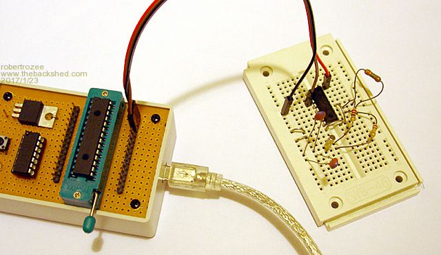 note the use of a 270k series resistor for the crystal, and 3M3 biasing resistor; i've read that one needs to be careful to not over-drive 32kHz watch crystals as it is quite easy to damage them. geoff: this could be a really neat addition to the micromite firmware, with the syntax of GETTIME extended thus: RTC GETTIME [, intpin] intpin would then be attached to the 1Hz output from the RTC, and if specified the RTC chip would be configured to active the 1Hz output. the mmbasic firmware could then provide the ISR and do the trimming internally, which would eliminate the jitter i've been seeing. just an idea - the above BASIC code adequately achieves the results required for my own application. cheers, rob :-) |
||||
| CaptainBoing Guru Joined: 07/09/2016 Location: United KingdomPosts: 2171 |
Hi Robert. Hope you are well. this is really interesting. I used another approach for the same problem without trimming the clock. I was only basing this on accurate time passage so your solution is better in that it corrects PWM and frequency measurement. Roman Black has an intesting article here (using Bresenham's work) which I used as the inspiration http://www.romanblack.com/one_sec.htm this maintains the accumulated error so while it may not give accurate intervals at any one point, over time it is very precise. I never finished playing with it (got overtaken with work) your post here has awakened the idea again. How did you determine the constants in the I and Trim calculations? cheers |
||||
| robert.rozee Guru Joined: 31/12/2012 Location: New ZealandPosts: 2542 |
i remember doing something similar based on bresenham's line algorithm 25 years ago when i was at uni: on the IBM PC hardware, timer interrupt ticks were derived from a 14.31818MHz NTSC colour burst crystal - normally divided by 4 in TV applications to give 3.579545MHz - that in the case of the PC was divided by 12, then by 65536, to give a timer tick rate of approximately 18.2 ticks per second. the 65536 divisor was programmable, and to increase the tick rate to 1mS required an approximately 1193.2 divisor. the (somewhat pedantic) solution i used was to dynamically change the divisor on each 'tick', selecting between 1193 and 1194 governed by brasenham's algorithm. as i recall the trick was to accumulate the under/over error at eack tick, then selected the divisor for the next interval (1193 or 1194) based upon the sign of the accumulated error. it was a pedantic solution in that it would have been just as accurate to use 1193 for 4 ticks, then 1194 for the 5th. the error introduced by this would have been less than the inaccuracies in the colour burst crystal. the only advantage of the more complex solution was that my code would keep exact time with the BIOS clock - i actually looked at the BIOS source code to find the exact crystal value assumed, and have a vague feeling that it may have been a fraction different from the 'correct' value derived from the official colour burst frequency. the choices of constants for calculating I and trim? best guesses! the I calculation is an approximation of the integral of the error (E) over time. the approximation is in discarding 'old' errors, and giving greater prominance to current (and more recent) errors. with constants of 0.8 and 0.2 the current error gets a 20% weighting, then previous one gets 16%, then 13%, etc. if you used constants of 0.99 and 0.01 (for instance) error terms going further back in time would be taken into account. the trim constants are even less scientific, 0.3 weighting for E was pulled out of thin air, and changing it didn't seem to make much difference. the sum of the two constants seemed to best be 1, as my feeling was that this should keep the offset error introduced close to the final trim value. cheers, rob :-) |
||||
| CaptainBoing Guru Joined: 07/09/2016 Location: United KingdomPosts: 2171 |
*sigh* getting all misty eyed... Those were the days... I was never happier than when I was knee-deep in Z80 assembler and weather radar |
||||
| The Back Shed's forum code is written, and hosted, in Australia. | © JAQ Software 2026 |
