
|
|
Forum Index : Microcontroller and PC projects : How to mount the MCP120 on an E100....
| Author | Message | ||||
Grogster Admin Group Joined: 31/12/2012 Location: New ZealandPosts: 9079 |
Hi all.  I have had several emails since the E100 kit was on offer, about how exactly to mount the MCP120 supervisory IC, so I thought a small thread was in order on this issue. The confusion tends to stem from the fact that the device is available in four different bond-out arrangements for the TO-92 package being used, meaning that there is not one common pin-out for this device as you might expect: 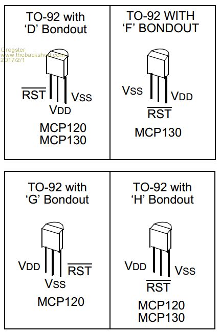 In the E100 kit, the device I used was the "G" bond-out version, and you MUST use that type if you are assembling you own kit. Mount it with the flat of the device in line with the bold line on the silkscreen - exactly the same as the neighbouring transistor: 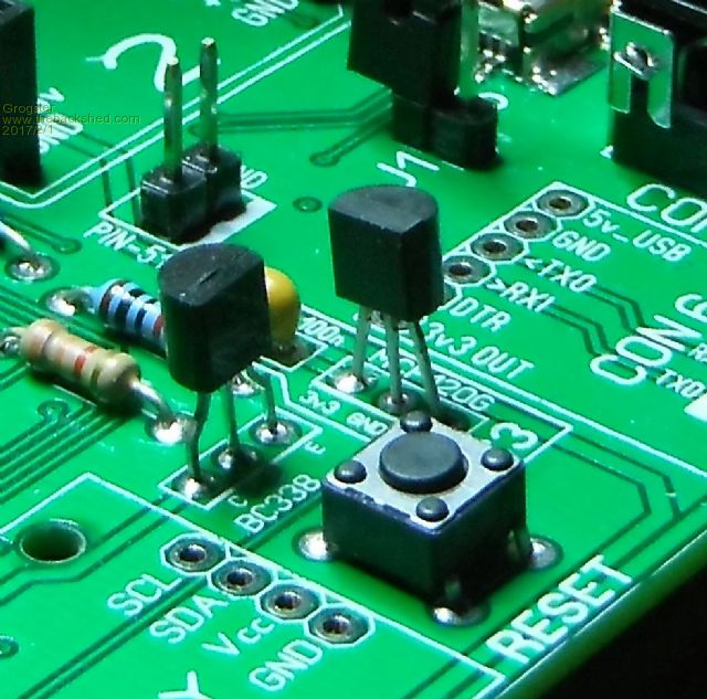 With any luck, this thread will help those who get confused by this device. I sympathise - having a TO-92 device with four different pin-outs would confuse most people. Smoke makes things work. When the smoke gets out, it stops! |
||||
bigmik Guru Joined: 20/06/2011 Location: AustraliaPosts: 2870 |
Grogs, That is just plain crazy to have that many pinouts for a simple 3 legged chip. I would adopt the SOT-23-3 device myself given that situation. Kind Regards, Mick Mick's uMite Stuff can be found >>> HERE (Kindly hosted by Dontronics) <<< |
||||
| bigmik Guru Joined: 20/06/2011 Location: AustraliaPosts: 2870 |
EDIT** You could then add 3 small THP pads to the SOT23 footprint so that if the end user chose they could stll use the Type G by splaying the centre pin out a couple of mm. Mik Mick's uMite Stuff can be found >>> HERE (Kindly hosted by Dontronics) <<< |
||||
| Grogster Admin Group Joined: 31/12/2012 Location: New ZealandPosts: 9079 |
Yes, that was obviously an executive Microchip decision!  Originally, it was an SMD, but somewhere along the design time-line, it was changed to TO-92. Probably to make it easier to assemble and to minimize the SMD part count. Smoke makes things work. When the smoke gets out, it stops! |
||||
