
|
|
Forum Index : Microcontroller and PC projects : Arduino Battery Voltage Controlled Relays
| Page 1 of 2 |
|||||
| Author | Message | ||||
Madness Guru Joined: 08/10/2011 Location: AustraliaPosts: 2498 |
I am starting this thread to help gpalterpower build an Arduino based device to switch his hot water heater on and disconnect a grid tie inverter when the voltage is getting too high on his solar battery bank. Here is a list of parts that are required, these are from suppliers that I have chosen after a quick search of AliEpress, you may find better quality and or cheaper if you do enough searching. Arduino Uno I know a Nano will do the job for about 1 dollar less but the Uno is easier to learn for a newbie Prototyping Shield Solid State Relay 2 off required Heat Sink For SSR 2 Off required 1 30K 0.5W resistor 1 5k 0.5W resistor 1 10k 0.5W resistor 1 120 Ohm 5W resistor 1 5.6V 1W Zener diode 1 TIP35C TRANSISTOR 1 100uf 63V electrolytic capacitor 1 100nf Ceramic Disc Capacitor, 50V 1 Monolithic Ceramic Chip Capacitor 10UF 50V I think that is everything, this includes the voltage regulator to run it off the battery bank voltage. Only hardware change needed for different battery voltages is 30K resistor. 12V 15K 24V 30K 48V 60K What we are setting out to do is turn on the SSR at a preset voltage in the Arduino to turn the hot water system and then at another slightly higher level turn off the GTI Inverter that is back feeding charge into the batteries via the DC off grid inverter. This can be programmed for any voltage level and also will include time delays for turn off and to turn back on to avoid rapid switching. Using an SSR will also allow the ability to use pulse width modulation to turn it on and off rapidly at a controlled rate to regulate the battery voltage at a set level rather hard on or off and causing voltage fluctuations. There are only 10 types of people in the world: those who understand binary, and those who don't. |
||||
| Madness Guru Joined: 08/10/2011 Location: AustraliaPosts: 2498 |
Here is the first part of the circuit 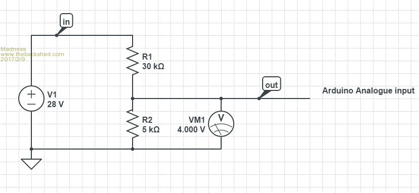 There are only 10 types of people in the world: those who understand binary, and those who don't. |
||||
| panky Guru Joined: 02/10/2012 Location: AustraliaPosts: 1120 |
@Madness Looks like an interesting project. With the regulator to supply power to the Arduino, you may have to do it in a couple of steps to keep the voltage drop across the regulator down as 28V down to 5V leaving 23V across the regulator will limit the current you can draw without over reaching the power capabilities of the regulator. Maybe a 28V to 15V reg that then feeds a 5V reg? Are you intending to have any form of display on the system? If so, the Micromite family may be worth considering in lieu of the Arduino - it can do evrything the Arduino can as far as analogue inputs and it is much simpler to program a really nice display with all the built in LCD panel display commands using the inbuilt Basic interpreter. There are versions with an Arduino shield interface - see the CircuitGizmos site - so a relay shield could be used. Lots of help here on the Back Shed for design and implimentation. We are a bit biased here toward the Micromite and MMBasic  but which ever way you go, good luck with the project and by all means ask questions. but which ever way you go, good luck with the project and by all means ask questions.Doug. ... almost all of the Maximites, the MicromMites, the MM Extremes, the ArmMites, the PicoMite and loving it! |
||||
gpalterpower Senior Member Joined: 19/07/2009 Location: AustraliaPosts: 175 |
Thanks Madness, Next time I go to town Ill pick the parts up from Autobarn. Marcus if it aint broke dont fix it!! |
||||
| Madness Guru Joined: 08/10/2011 Location: AustraliaPosts: 2498 |
Hi Doug, I am going to use the same circuit as Oztules for the power supply in the Ozinverter control board. It has no problem delivering 5V from a 48 volt battery bank which is quite often up near 60 volts while charging. As for micromites, I have no experience with them other than with fly spray. The Arduino's are cheap at around $5 so I don't see that you would save much any way. A display can be added, but at this point I am just trying to keep it simple as Marcus is a complete newbie to microcontrollers. There are only 10 types of people in the world: those who understand binary, and those who don't. |
||||
| MicroBlocks Guru Joined: 12/05/2012 Location: ThailandPosts: 2209 |
I think the fact that it has to be simple is a huge point for a micromite as the language to control stuff is so much easier for a 'newbie'. I use arduino's often and they surely get the job done, it is just the development environment and the language (C/C++) that can be very steep for a beginner. Microblocks. Build with logic. |
||||
| Madness Guru Joined: 08/10/2011 Location: AustraliaPosts: 2498 |
Feel free to go ahead if you want I am just doing this to help him out in the way I know. I was going to write the code to do the job so all he has to do is upload it. I have not found the Arduino difficult, but please go ahead and do it with your micromites if you want to I did not realise that this is micromite forum. There are only 10 types of people in the world: those who understand binary, and those who don't. |
||||
| Clockmanfr Guru Joined: 23/10/2015 Location: FrancePosts: 437 |
Hi Madness, Just you carry on with the Arduino. I will make one from your instructions. I will point folk who ask me to here, most are absolute beginners, so don't worry about giving to much info, more info the better. My philosophy .... keep it simple, make it robust, and keep it cost effective. Everything is possible, just give me time. 3 HughP's 3.7m Wind T's (14 years). 5kW PV on 3 Trackers, (10 yrs). 21kW PV AC coupled SH GTI's. OzInverter created Grid. 1300ah 48v. |
||||
| Madness Guru Joined: 08/10/2011 Location: AustraliaPosts: 2498 |
Okay here is the full circuit diagram, hopefully there are no mistakes.  This should all fit on the prototyping shield as per post 1. However the 2 SSR's will be seperate and you will need to allow room for a heatsink for the TIP35c. I will also include a Serial 2X16 LCD display in the code, but it will work just the same with no display. I will work on the code and then it will be ready to use when you have built the PCB. I have made a PDF of the circuit that wil be easier to read. 2017-02-10_124644_Arduino_dump_controller.pdf There are only 10 types of people in the world: those who understand binary, and those who don't. |
||||
| gpalterpower Senior Member Joined: 19/07/2009 Location: AustraliaPosts: 175 |
Thanks Madness, Was looking at the required parts thru Ali Express. Im just going thru ebay as I have a pay pal account there. Seems Ali Express dosent deal with PP. Is this compatible. http://r.ebay.com/36f0lL. Do I need a lead for the board? Marcus ps Thanks for the PDF. if it aint broke dont fix it!! |
||||
| Madness Guru Joined: 08/10/2011 Location: AustraliaPosts: 2498 |
Hi Marcus, So long as you have the right USB cable already that is fine, once you have it up and running you won't need it then. The Arduino will run off the USB but the circuit I have given you provides power directly from your battery bank. You do need the USB cable to upload the programme to the Arduino. The Arduino in the Ebay link is fine, would not hurt to get a couple as once you start playing with them you will find other things to do with it. Warning it can become addictive. There are only 10 types of people in the world: those who understand binary, and those who don't. |
||||
| gpalterpower Senior Member Joined: 19/07/2009 Location: AustraliaPosts: 175 |
Madness, I did notice that some came with a cable but it seemed they had a different output port other that a USB. Like this one http://r.ebay.com/Q8c3xL . would this be better? Slightly more more expensive but would be here way sooner. Marcus if it aint broke dont fix it!! |
||||
| johnmc Senior Member Joined: 21/01/2011 Location: AustraliaPosts: 282 |
Good day, Thanks Madness. I am rounding up the parts required for the Arduino voltage control. Cheers john johnmc |
||||
| JackS Newbie Joined: 04/03/2009 Location: New ZealandPosts: 8 |
Hi guys Any updates? how did it work out? Anybody try this circuit with PWM? This looks like what I have been looking for  |
||||
| panky Guru Joined: 02/10/2012 Location: AustraliaPosts: 1120 |
Hi, I too would be interested in how it all turned out? Also I would be very interested to see a full system diagram if that is possible? Nice work. panky ... almost all of the Maximites, the MicromMites, the MM Extremes, the ArmMites, the PicoMite and loving it! |
||||
| George65 Guru Joined: 18/09/2017 Location: AustraliaPosts: 308 |
If anyone is looking for a pre-built unit, I got a couple of these Voltage monitors and have been using them to control my Hot water heater from the solar with a GTI. The unit monitors the line voltage in the circuit and when it hits a pre set level which is above the normal Voltage indicating the GTI is pumping power back into the grid, the unit activates and turns on the heater. I am using it with a PWN controller atm and all is working perfectly. You could use this with a relay if you wanted to go direct without the PWM as the monitor is only rated for 6 amps so a relay will in most cases be required to drive the element at full power. The unit has a hysteresis so when the voltage drops from the load of the heater it does not drop out again and keep switching on and off. The upper, lower and hysteresis levels are all configurable so you can set the thing anywhere you may need. There are different models to cover different voltages. Very happy with the way these things are working and every bit as good as the units 20X more expensive I have seen for controlling water heaters. If you are like me and have trouble with putting together Arduino or other electronic setups, These could be a solution even if as cheap as the DIY alternative. |
||||
| Madness Guru Joined: 08/10/2011 Location: AustraliaPosts: 2498 |
If you look here at this charge controller it will do PWM control of hot water systems etc running off 48VDC. You can buy 48V water heater elements on Aliexpress and other solar suppliers. There are PCBs that I am just about to get made and will also include RS485 which is handy if you want to control something up to 1,200M away. What are you actually want to do Jack? There are only 10 types of people in the world: those who understand binary, and those who don't. |
||||
| JackS Newbie Joined: 04/03/2009 Location: New ZealandPosts: 8 |
Hi Madness Thank you for your quick response. I'm after Dump controllers for 24 & 48 volt to prevent overcharging my Nicad batteries with Hydro, solar & a back up diesel driven smart drive if that makes any sense This looks like something I might be able to build even though I've never done anything with a micro before Unfortunately Ill be heading back home tomorrow & won't have internet for a few weeks |
||||
| Madness Guru Joined: 08/10/2011 Location: AustraliaPosts: 2498 |
The charge controller could be reconfigured as a dump controller, however do you need to dump power or if you reduce the incoming power with PWM will there be a problem? There are only 10 types of people in the world: those who understand binary, and those who don't. |
||||
| JackS Newbie Joined: 04/03/2009 Location: New ZealandPosts: 8 |
I don't want to run the pelton wheel unloaded as the RPM And open circuit voltage go higher than I want I like the idea of using the excess power from the hydro & solar for water heating. 120 volt water heating elements should work as a load 7.2r about 500 watt @60v for a 2kw 120v element judging buy my experiments with 240 volt elements |
||||
| Page 1 of 2 |
|||||
| The Back Shed's forum code is written, and hosted, in Australia. | © JAQ Software 2026 |
