
|
|
Forum Index : Microcontroller and PC projects : Micromite eXtreme64 and PCB
| Author | Message | ||||
| matherp Guru Joined: 11/12/2012 Location: United KingdomPosts: 8605 |
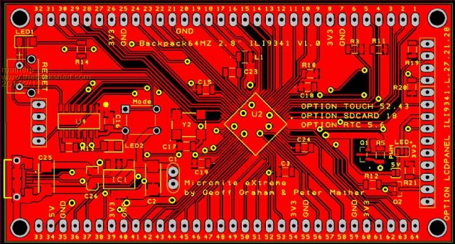 I originally dropped support for the 64-pin MZ chip as it was proving increasingly difficult to reconcile the additional functionality in the 100-pin eXtreme with the limited pin count on the 64-pin MZ whilst also trying to maintain some pin compatibility with the 64-pin MM+. However, now the MZ code is reasonably stable I decided to revisit this and have created a fork of the code specifically for the 64-pin chip. 2017-02-11_151415_MMX64V5.3.04.zip This has a ground-up pin allocation to get the best usage of the chip with minimum overlap of special functions. The eXtreme64 does have some reduced functionality compared to the 100 and 144-pin code-set. Only one I2C port Only two SPI ports No VGA support No 16-bit parallel SSD1963 support Otherwise everything in the 100/144 pin versions is there and works identically. The question is what sort of PCB would suit? I've designed a 2.8� ILI9341 sized board as above and the prototypes of this are on order. Hopefully WhiteWizard will add this board to his portfolio  but I'll release gerbers as soon as the design is checked out. Because the PCBs are comparatively small (93.5mm x 50mm) they are also cheap - USD23 for 10 including shipping to the UK. but I'll release gerbers as soon as the design is checked out. Because the PCBs are comparatively small (93.5mm x 50mm) they are also cheap - USD23 for 10 including shipping to the UK.The board is powered through the micro-USB connector which also acts as the console via a PIC16F1455 with the USB/UART/Programmer code installed. The PCB is on a 0.1" grid and can be plugged directly into a breadboard for connecting additional components. The 2.8" ILI9341 TFT display, if fitted, mounts over the top of the components on the board and provides the SDcard slot. Every pin on the 64-pin MZ is broken out in the expected order. The bottom of the PCB is silk-screened with full details of the special function uses of each pin as below. Other than the console, there is no on-board functionality provided except for transistors to allow for PWM control of the TFT backlight. SMD components are chosen to be easy to hand solder (1206, SOIC, 7x5 oscillator). |
||||
| WhiteWizzard Guru Joined: 05/04/2013 Location: United KingdomPosts: 2794 |
This will indeed be the case - as soon as I have built & tested one For everything Micromite visit micromite.org Direct Email: whitewizzard@micromite.o |
||||
| Zonker Guru Joined: 18/08/2012 Location: United StatesPosts: 761 |
Thank you much Gent's..! I love all the work that has gone into these projects..!! Having several choices of PCB engines to use in our projects makes things easier for everybody..! Hopefully, many more people will be discovering how easy this awesome platform is to use and integrate into finished gadgets...  |
||||
| Cremo Newbie Joined: 21/07/2015 Location: ItalyPosts: 34 |
I am interested to this board. I would also to know the status of board for PIC32MZ with 144pins. Best regards. Pietro |
||||
| sagt3k Guru Joined: 01/02/2015 Location: ItalyPosts: 313 |
Hi matherp Thanks for your great support and Geoff. I'm very interested for 64pin. Is it possibile to have manual "Micromite_eXtreme_Manual" updated with 64pin variant ? Can you specify what PIC32MZ64x pin is supported ? Thanks sagt3k |
||||
| WhiteWizzard Guru Joined: 05/04/2013 Location: United KingdomPosts: 2794 |
MMX144 Modules are steadily being constructed and shipped out in the sequence that they were ordered. I was hoping to have most despatched last week, but a MMX firmware issue added a small delay (Peter fixed it immediately it was identified). I will continue to PM/email people directly as theirs are despatched so do keep an eye on your inbox in the coming days For everything Micromite visit micromite.org Direct Email: whitewizzard@micromite.o |
||||
| isochronic Guru Joined: 21/01/2012 Location: AustraliaPosts: 689 |
Is there a working version in hardware yet ? |
||||
| WhiteWizzard Guru Joined: 05/04/2013 Location: United KingdomPosts: 2794 |
Not yet on this PCB design . . . For everything Micromite visit micromite.org Direct Email: whitewizzard@micromite.o |
||||
| matherp Guru Joined: 11/12/2012 Location: United KingdomPosts: 8605 |
PIC32MZ2048EFH064-250I/PT - preferred option PIC32MZ2048EFH064/PT PIC32MZ2048EFG064/PT - cheapest option PIC32MZ2048EFM064/PT Full BOM as follows: Capacitor 1206 0.1uF * 8 Capacitor 1206 1uF * 1 Capacitor 1206 22uF * 1 Capacitor ceramic 1uF 2.5mm lead pitch * 1 Capacitor Tantalum 100uF * 2 e.g. TR3C107K010C0100 Resistor 1206 10K * 6 Resistor 1206 4K7 * 1 Resistor 1206 1K0 * 1 Resistor 1206 330R * 2 LED 1206 * 2 e.g. KPTD-3216SRC-PRV Inductor 1206 * 1 e.g. Murata LQM31PN1R0M00L npn Transistor SOT23 * 1 e.g. BC817-40 p-channel mosfet SOT23 * 1 e.g. IRLML6402TRPBF PCB switch Tyco 1825967-2 * 1 PCB switch Tyco FSMRA4JH * 1 Micro-USB connector Amphenol FCI 10118192-0001LF * 1 PIC16F1454-I_SL * 1 Oscillator 24MHz 7x5mm * 1 e.g. SG8002CAPCB24MHZ 3.3V LDO regulator * 1 e.g. LD1117S33CTR |
||||
| sagt3k Guru Joined: 01/02/2015 Location: ItalyPosts: 313 |
Hi matherp Can wen have complete pins list? I don't see from 33 to pin 40. I have PIC32MZ2048EFG064/PT, I need always active oscillator 24mhz ..right? Thanks sagt3k |
||||
| matherp Guru Joined: 11/12/2012 Location: United KingdomPosts: 8605 |
Yes These are USB and power pins see attached manual and PIC32MZ datasheet 2017-02-12_103829_Micromite_eXtreme_Manual.pdf |
||||
| robert.rozee Guru Joined: 31/12/2012 Location: New ZealandPosts: 2294 |
peter, you may wish to add a 10k pullup on the 1455's select input. i've found this necessary when using certain small/cheap SMD switches to prevent 'chattering' when the button is pressed and held down to reset the micromite. presumably weak pullup + dodgy button = pin 4 hovering mid-rail for too long and causing problems. cheers, rob :-) |
||||
| matherp Guru Joined: 11/12/2012 Location: United KingdomPosts: 8605 |
PCBs have arrived - just need to build one now  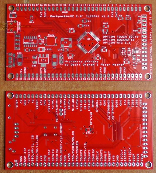 |
||||
| WhiteWizzard Guru Joined: 05/04/2013 Location: United KingdomPosts: 2794 |
NICE Do you have a RS part No for that USB socket please? WW For everything Micromite visit micromite.org Direct Email: whitewizzard@micromite.o |
||||
| matherp Guru Joined: 11/12/2012 Location: United KingdomPosts: 8605 |
10118192-0001LF from RS = 863-2986 but I got them from Farnell |
||||
| matherp Guru Joined: 11/12/2012 Location: United KingdomPosts: 8605 |
I like it when things work first time and don't need any changes Contact WW if interested in a PCB 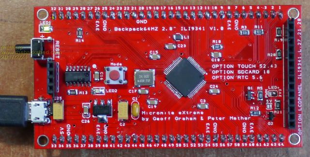 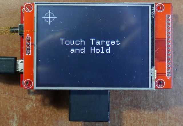 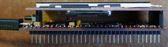 |
||||
| CaptainBoing Guru Joined: 07/09/2016 Location: United KingdomPosts: 1995 |
that looks sweet. nice job |
||||
