
|
|
Forum Index : Microcontroller and PC projects : Pir sensor not working
| Page 1 of 2 |
|||||
| Author | Message | ||||
| rallyman Newbie Joined: 15/02/2017 Location: HungaryPosts: 9 |
Hello, Could you please me with my project? I would like to make a setup with a PIC32MX170256D, one led and one pir sensor. Some years ago I used arduino and C language, but now I use this PIC and mmedit software with "BASIC" programming language. I can blinking a led already and now I want to create a configuration where the led blinks when the pir sensor detects motion. Here is my BASIC configurtaion: OPTION EXPLICIT CONST PIRLED=1:SETPIN PIRLED,DOUT CONST PIRPIN=2 SETPIN PIRPIN,INTB,ALERT,PULLUP DIM SIGN=0 'PROGRAM START DO PIN(PIRLED)=0 DO WHILE SIGN=0 LOOP MOTIONACTION SIGN=0 LOOP SUB ALERT SIGN=1 END SUB SUB MOTIONACTION PRINT "MOTION DETECTED!" PIN(PIRLED)=1 PAUSE 1000 PIN(PIRLED)=0 END SUB END I have the led connected to PIN-1 OUTPUT I have the pir sensor output connected to PIN-2 and use a pullup register to detect the motion. The situation is that I start burn the program into the PIC and run, then it starts and immediately blink the led one time and print that motion detected. After that I never can force the pir sensor to detect any motion :( Of course, I played a lot with the sensitivity and delay pot on the pir, but it did not helped. Maybe there is sg wrong with my BASIC code. I am more familiar with C language than BASIC, but I do not have any usb adapter to upload the config in C version. MPLAB can not discover my usb adapter, so mmedit is the only sw now what I can use to upload the config. ANd mmedit is for BASIC as I know. Could you please help me with my source code? PS: I have ordered a PICKIT3 adapter, to be able to use MPLAB and C code. It is on its way. Many thanks! have a good day! |
||||
| WhiteWizzard Guru Joined: 05/04/2013 Location: United KingdomPosts: 2985 |
@rallyman, A few of things first: 1> Which version of MMBASIC are you using? If you can see a 'Welcome' message when you reset the MicroMite, then the version number will be in there. Or, at the command prompt, simply type PRINT mm.ver 2> With your PIR output, is it active high, or low, when movement is detected? I assume LOW bearing in mind you are using the software PULLUP on the PIR input (pin 2) 3> Can you confirm the PIR sensor is not faulty? 4> Does your PSU have enough power - not knowing if you're powering everything off the same PSU/vReg? Also: In your setup for Pin 2 you are using INTB (interrupt triggered on both high or low change). It maybe better to use INTL (assuming PIR is 'active low'). WW |
||||
| WhiteWizzard Guru Joined: 05/04/2013 Location: United KingdomPosts: 2985 |
IF you are not wanting the MicroMite to do anything else, then consider the following code: OPTION EXPLICIT CONST PIRLED=1:SETPIN PIRLED,DOUT PIN(PIRLED)=0 'ensure LED off to start with CONST PIRPIN=2 'PROGRAM START DO DO WHILE PIRPIN=1:LOOP ' endless loop while no motion (i.e. PIR input high) DO WHILE PIRPIN=0 ' if here then motion detected PIN(PIRLED)=1 ' LED on PAUSE 200 ' but only briefly PIN(PIRLED)=0 ' before turning LED OFF again PAUSE 200 ' bit more of a delay (so LED can Flash if movement still occurring) LOOP ' see if still moving LOOP ' if no movement - then go back to wait for next movement END WW |
||||
| panky Guru Joined: 02/10/2012 Location: AustraliaPosts: 1127 |
@WW There alsoneeds to be a SETPIN statement for PIRPIN to set it as DIN near the start of your code example. Doug. ... almost all of the Maximites, the MicromMites, the MM Extremes, the ArmMites, the PicoMite and loving it! |
||||
TassyJim Guru Joined: 07/08/2011 Location: AustraliaPosts: 6534 |
Hi, I tested your code here and it runs OK The only change I made was to the pins used. That was to make it easier for me to use my test setup. I tested the input by shorting my pin to ground. Test you PIR output and try different pins. Jim VK7JH MMedit |
||||
| TassyJim Guru Joined: 07/08/2011 Location: AustraliaPosts: 6534 |
On the MX170, pin 1 is RESET so it should give a warning if you tried to use it for the LED VK7JH MMedit |
||||
| rallyman Newbie Joined: 15/02/2017 Location: HungaryPosts: 9 |
Thank you guys, I am in work now, but when I arrived home, I will try all these things and get back to you! thx |
||||
| WhiteWizzard Guru Joined: 05/04/2013 Location: United KingdomPosts: 2985 |
Only on the 28pinner. Tallyman is using the PIC32MX170...D which is a 44pinner and therefore is fine to use pins 1 & 2. I suspect his PIR unit - so recommend he does the 'shorting out test' like TassyJim  |
||||
| rallyman Newbie Joined: 15/02/2017 Location: HungaryPosts: 9 |
Hello, Thank you for the replies. I have uploaded some photos about my setup: https://1drv.ms/f/s!AjKA5kkGUL6Sgqtemq3N1lVOFgc9ZA I have tried 4 different pir sensors. I have also tried out different pins on the PIC. Now the situation with the setup on the photos, that I upload the code succesfully, then it starts, the led blink once at the beginning, and after that never blink again. I have also tried different "time" and "sensitivity" settings on the pir sensor. Many thanks. Regards. |
||||
| WhiteWizzard Guru Joined: 05/04/2013 Location: United KingdomPosts: 2985 |
@rallyman, Why not simply forget the sensor for now, and just short out the PIR pin to 0V to simulate movement This worked for TassyJim, and will help identify if it is a PIR issue, or a MM/Code issue. IF it turns out to be an PIR issue then you need to be certain what the PIR's output means. Not all are at a logic level! WW |
||||
| Frank N. Furter Guru Joined: 28/05/2012 Location: GermanyPosts: 1100 |
Hi Rallyman, are you sure your polarity is right? It seems that you use brown as GND and orange as VCC. But in this photo is the polarity changed??? 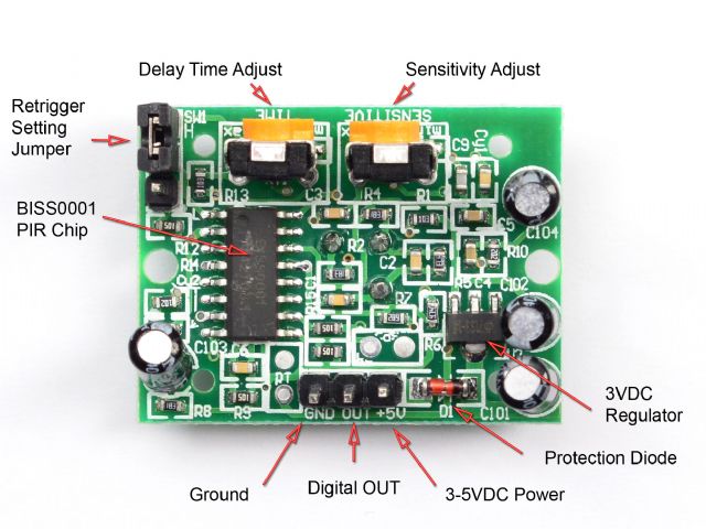 Frank |
||||
| WhiteWizzard Guru Joined: 05/04/2013 Location: United KingdomPosts: 2985 |
Is there enough power to drive the PIR? IF it is 3v3, then it looks like you're powering from the USB module which may have limited available power (purely depends on how you are powering things which is not obvious from the photos) |
||||
| rallyman Newbie Joined: 15/02/2017 Location: HungaryPosts: 9 |
Hello, This is my pir: Pir sensor datasheet In this I can see: 3.3V & 5V operation with <100uA current draw My only power source is the USB now, what is connected to USB2 port on my desktop computer. What do you think? PIC32 has 3,3V and 5V output pin, have connected the pir to the 5V now. (yes, red is the VCC and brown is ground) I think it should be enough for this setup to get 1 pir work. I can not change the VCC and ground, because it is clearly written on my pir: 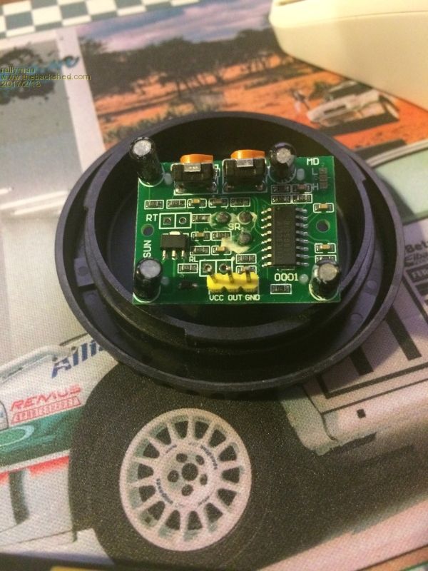 I try to debug my code, that is it ever runs the "ON" loop... Thanks |
||||
| WhiteWizzard Guru Joined: 05/04/2013 Location: United KingdomPosts: 2985 |
OK - Two major things: 1: Looks like you need to set the jumper option in the top right hand corner (as in your photo) marked with H and L Reading the data sheet, I would personally short both the lower two pads (i.e. H) to provide a continuos logic high level when movement is detected 2: The output is active high (note to others: this 'active level' is NOT determinedt by the jumper link mentioned in the above point). We have been supplying code that ONLY works on active LOW (see below for more info) So, first you need to short out a jumper option. THEN you need to change your code to work on a 'high' input to indicate motion. Hope the above information helps you out WW EDIT: IGNORE MY pre-edited comment regarding POWER - I was looking at the incorrect data sheet  |
||||
| WhiteWizzard Guru Joined: 05/04/2013 Location: United KingdomPosts: 2985 |
To modify your original code to work on 'active high', then make the following highlighted changes WW OPTION EXPLICIT CONST PIRLED=1:SETPIN PIRLED,DOUT CONST PIRPIN=2 SETPIN PIRPIN,INTH,ALERT,PULLDOWN DIM SIGN=0 'PROGRAM START DO PIN(PIRLED)=0 DO WHILE SIGN=0 LOOP MOTIONACTION SIGN=0 LOOP SUB ALERT SIGN=1 END SUB SUB MOTIONACTION PRINT "MOTION DETECTED!" PIN(PIRLED)=1 PAUSE 1000 PIN(PIRLED)=0 END SUB END |
||||
| rallyman Newbie Joined: 15/02/2017 Location: HungaryPosts: 9 |
thanks! 1) my sensor is default H 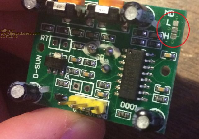 but I also have pirs with jumper: 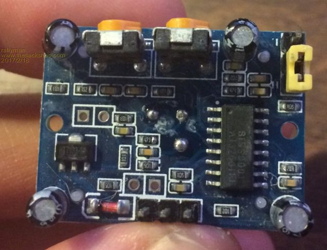 So I have changed my code to pulldown version. Now,it never gets any motion detected :( I have also tried to short out the pir_out leg working like this: 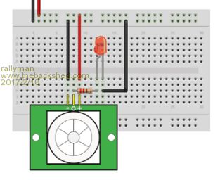 This is stange, because I can never blink the led :( |
||||
| WhiteWizzard Guru Joined: 05/04/2013 Location: United KingdomPosts: 2985 |
Remove the PIR altogether and just have your code running. Then take a wire and short your PIR input pin to +3v3 and see if when shorted it blinks the LED output! This test is the best approach now before attempting to re-connect the PIR Let us know if this works. WW |
||||
| WhiteWizzard Guru Joined: 05/04/2013 Location: United KingdomPosts: 2985 |
Also, are you giving your PIR module enough time to 'settle' after the initial power up. According to data sheet, you want to allow a minute of 'no movement' time for it to settle. So I suggest to first try the above test with just a wire jumper connected to 3v3 to simulate movement (this ensures your MM is ok, along with the code. Then add the PIR back in (assuming the above test works ok) and leave it in a 'quiet area' for a couple of minutes. THEN, and only then, try waving your hand above the detector! Good luck . . . WW |
||||
| rallyman Newbie Joined: 15/02/2017 Location: HungaryPosts: 9 |
OMG :( I have create a setup wiht my arduino panel and it works fine :( there is sg wrong with the GRN and 5V output on the PIC! Now i have a setup where I get the GRN and 5V from the arduino panel via usb and I get the pir_out and led_pin connected the the PIC pins. Now all the codes and wires are working fine... soon comes some picture |
||||
| WhiteWizzard Guru Joined: 05/04/2013 Location: United KingdomPosts: 2985 |
The LED will not blink with the above code as the interrupt is only triggered once while there is movement. Put it another way, while there is movement, upon detection the LED will flash for one second, and then remain off. Your code can be 'modified' in various ways to achieve FLASHING but for now, just go with ON for movement, and OFF for no movement with code I will post next |
||||
| Page 1 of 2 |
|||||
| The Back Shed's forum code is written, and hosted, in Australia. | © JAQ Software 2026 |
