
|
|
Forum Index : Microcontroller and PC projects : Backpack144 Extreme Newbie Help
| Page 1 of 3 |
|||||
| Author | Message | ||||
retepsnikrep Senior Member Joined: 31/12/2007 Location: United KingdomPosts: 134 |
Got my extreme backpack from WW and screen as per the link posted on forum from hong kong. Got the green flashing light on the rear after reset. Nothing at all on attached lcd display.. :( Backlight appears to be on. I note there is a tiny pot on the back of the screen ? With a VGA screen plugged in I get the splash screen as expected. Also have the Composite usb device exclamation mark in device manager. Have tried (installed) microblocks driver for this (right click install etc). No change even after reboot. Ideas? What psu (voltage range/current etc) is best for the power jack on the board. What are the lengths/specs/part numbers for the pcb standoffs for the display mounting. Thanks Gen1 Honda Insights. |
||||
| WhiteWizzard Guru Joined: 05/04/2013 Location: United KingdomPosts: 2962 |
Hi Peter, Good to here your MMX144 arrived safely (I did see they also attempted a delivery yesterday!) You cannot have both displays (i.e. VGA and TFT at the same time - it only drives one display which has to be configured with OPTION LCDPANEL and then either VGA or SSD.... Regarding the driver; search for the Silicon_Chip_USB_Serial_Port_Driver.zip from Silicon Chip website (possibly third link down - but keeps changing position) Alternatively, if you have a USB-to-UART module at hand, then use that and connect to the Console Input on the MMX144. This is better as Windoze doesn't drop the connection whenever the MMX is reset  As in my email to you, I have left your MMX144 set for VGA operation. Do a quick OPTION LIST at the command prompt and you will see the options that have been set (and their parameter values). I honestly don't remember if I set OPTION KEYBOARD UK, but if you have a PS2 keyboard lying around, then plug it in to the PS2 keyboard input (next to the uSD socket). Regarding PSU, I recommend a 7.5V PSU (if using an external PSU) as this means the vReg won't warm up too much. I was testing with a 9v PSU and it was getting rather warm. My actual preference is to use a 5v 2.1A phone charge into the USB, and then use a console connection to communicate with the MicroMite. OR better still, have the CONSOLE on the attached screen, plug in a PS2 keyboard, and then it is a standalone system. Choices available - so whatever works best with what you have! Regarding standoff length - simply see what minimum clearance you need with your particular TFT, and then buy something that size or greater. Do let us know how you get on with the Silicon Chip driver WW |
||||
| matherp Guru Joined: 11/12/2012 Location: United KingdomPosts: 11143 |
NO!!! If the 16F1455 is installed you would be driving two outputs together If you are using W10 then no driver is needed. You are plugged into the port labelled USB Client? I use 12mm M3 spacers to mount the TFT e.g. these |
||||
| WhiteWizzard Guru Joined: 05/04/2013 Location: United KingdomPosts: 2962 |
 Sorry - my testing process coming out when PIC1455 not inserted - SORRY |
||||
| matherp Guru Joined: 11/12/2012 Location: United KingdomPosts: 11143 |
Here is a screen mounted on 12mm spacers and using 22mm spacers as stands to sit flat on the desk 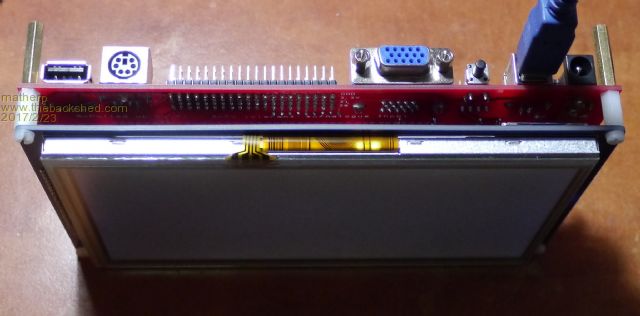 |
||||
| retepsnikrep Senior Member Joined: 31/12/2007 Location: United KingdomPosts: 134 |
I'm using XP. Sorry missed that it was configured for the VGA. I thought the default would be an lcd panel. I'll try and dig up a ps2 keyboard. Thanks for the info. Gen1 Honda Insights. |
||||
| retepsnikrep Senior Member Joined: 31/12/2007 Location: United KingdomPosts: 134 |
I'm still stuck with the composite USB device issue. Tried all the available driver versions. I suspect my PC USB port power output is not man enough to drive the board properly. So the driver fails to install.  Gen1 Honda Insights. |
||||
| matherp Guru Joined: 11/12/2012 Location: United KingdomPosts: 11143 |
Just put the header to "JACK" and use an external 7.5V power supply. Then try the USB again. That way the USB isn't supplying any power. |
||||
| WhiteWizzard Guru Joined: 05/04/2013 Location: United KingdomPosts: 2962 |
Peter, Can I suggest that you disconnect any TFT you may have connected to the MMX144 (to minimise current draw). Also, IF continuing to use a USB lead to power the MMX, then try a different USB cable as some 'thin ones' are really poor at suppling enough current. And do make sure the power header (between the voltage regulators) has a jumper-link in the correct position for the power source you are using. When you have initially powered up, PRESS THE RESET BUTTON on the MMX before doing anything else and check that the green HeartBeat (HB) LED (next to the uSD socket) is pulsing at 1Hz. If not, then the MMX is not 'alive'. I know you mentioned this in the first post, but you may have forgotten to 'reset the MMX" in later attempts. Once you have a 'pulsing' HB LED, then look to load the drivers . . . WW |
||||
| retepsnikrep Senior Member Joined: 31/12/2007 Location: United KingdomPosts: 134 |
I'm still struggling. I pulled the PIC 16F chip from the board as i could not get it to talk with any of the USB XP drivers suggested. Always had that exclamation mark in device manager. I now have a serial converter connected to the console pins. I have the com port / baud rate correct etc. The console prints gibberish when I press the reset button on the extreme. But the gibberish looks about the right amount of gibberish to be the splash screen. Ideas before it goes in the bin... Very frustrated.. 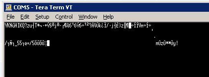 Gen1 Honda Insights. |
||||
| lizby Guru Joined: 17/05/2016 Location: United StatesPosts: 3730 |
Have you tried the reset method from the manual: Sending a stream of exclamation marks (!) to the console Rx pin at 34800 baud during its startup. In the first 100 mS after powering up the Micromite will set the console to 34800 baud and check to see if an exclamation mark is received. If so, it will then wait for two seconds to see if it is going to get more than 30 of them in that time. If this is the case the Micromite will reset itself to its initial defaults and send the message "MMBasic reset completed" to the console. This reset can be accomplished by simply setting the terminal emulator to 38400 baud and holding down the exclamation key while powering up the Micromite (on most keyboards this requires holding down shift and the number one key). This will even work if the console has been set to a non standard baud rate. PicoMite, Armmite F4, SensorKits, MMBasic Hardware, Games, etc. on FOTS |
||||
| matherp Guru Joined: 11/12/2012 Location: United KingdomPosts: 11143 |
Do the reset as proposed Put the 1455 back and use this driver on the documentation tab. This is known to work with XP. Otherwise I suggest you return to WW to sort out for you |
||||
| WhiteWizzard Guru Joined: 05/04/2013 Location: United KingdomPosts: 2962 |
Peter Do make sure you try the Driver in PeterM's link. I can also email it to you but some email servers 'strip' the attachment. Also make sure the 14pin PIC is also inserted the correct way round (pins 1 & 14 nearest the buzzer). If this still fails to work for you then I am more than happy to give you a call later this evening, or tomorrow morning and we can go through a few things over the phone. Let me know when is best for me to contact you if you need one-to-one support . . . WW |
||||
| retepsnikrep Senior Member Joined: 31/12/2007 Location: United KingdomPosts: 134 |
I re-downloaded the driver and put the chip back, the driver still fails to load correctly. With the below message .. 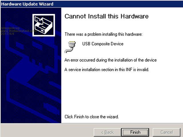 I don't see how to send commands with tera term connected. I don't have a PS2 keyboard available. I expected to be able to control/configure the extreme via TT and the keyboard on my PC. I can't do the reset to send exclamation marks as i can't see how to send them with TT.. My PC keyboard does not do anything with TT.. Sorry if I am being very dim.. The Extreme i'm alive light is flashing away. Are the Console pins 5v tolerant.. Most USB/Serial adapters are 5V? Gen1 Honda Insights. |
||||
| retepsnikrep Senior Member Joined: 31/12/2007 Location: United KingdomPosts: 134 |
Standby I now have MMEDIT Chat doing something via console connection!!! OPTION LIST working.. Maybe nearly there.. Gen1 Honda Insights. |
||||
| WhiteWizzard Guru Joined: 05/04/2013 Location: United KingdomPosts: 2962 |
Peter, Sounds like you're making some progress there but do get in touch and I will call you to discuss over the phone (it will be much quicker than multiple posts/emails/PMs). Sounds like TT and the loading of the MicroChip driver are your issue(s). The Console pins on the MMX144 module were there more for our test purposes and therefore have not got protection in for 5V. So recommend a 1K5 (ish) value resistor in the 'external USB-to-Serial' Tx line only (i.e. to the Rx signal on the MMX144). Anyway - see how you get on and do get in touch directly if you need to! WW |
||||
| retepsnikrep Senior Member Joined: 31/12/2007 Location: United KingdomPosts: 134 |
OK thanks now just need the exact command for the 7" SSD1963 LCD Panel. I can't see from the extreme documentation which are the correct pins for the panel. RD pin and LED Control. The Plus manual gives this example.. 100-Pin Example The Explore 100 board with the 100-pin Micromite Plus uses the following pi Pin 48 is the SSD1966 LED_A control Pin 6 is the SSD1963 RD pin Pin 1 is the touch Chip Select Pin 40 is the touch IRQ input Pin 39 is the touch click output (see the next chapter) Pin 47 is the SD card Chip Select The corresponding configuration commands are: OPTION LCDPANEL SSD1963_5, LANDSCAPE, 48, 6 So im thinking OPTION LCDPANEL SSD1963_7_16, LANDSCAPE,? ,? What are those ? pins? Gen1 Honda Insights. |
||||
| matherp Guru Joined: 11/12/2012 Location: United KingdomPosts: 11143 |
The RD pin number is silkscreened on the PCB - 142 The LED pin isn't used as the ssd1963 has its own control on the backlight. Make sure the 0-ohm jumper on the backlight control on the TFT is set to 1963_PWM I tend to use: which puts the main cables at the back of the unit. PS: life is much easier with W10 |
||||
bigmik Guru Joined: 20/06/2011 Location: AustraliaPosts: 2979 |
@Peter, Phil, As this is an obviously popular board, (I love my Extreme144) and the firmware is changing fairly regularly, have you considered using the Back Shed Document Library to host all of the documents and associated drivers and latest firmware etc? I have used this for MuP V3 and I find it a very good, but little used, repository. Kind Regards, Mick Mick's uMite Stuff can be found >>> HERE (Kindly hosted by Dontronics) <<< |
||||
| bigmik Guru Joined: 20/06/2011 Location: AustraliaPosts: 2979 |
Hi retepsnikrep, Here is some option settings that worked for me (Thank you Phil for educating an `old dog') OPTION RESET (to clear everything). IF you don't want to do this, then I alternatively recommend you type OPTION LCDPANEL DISABLE (to 'remove' any existing screen setup - this is important) OPTION CPU 252 (maximum speed - and it does make a difference!) OPTION LCDPANEL SSD1963_7_16,L,,142 (note the double comma in there!) OPTION LCDPANEL CONSOLE 2,RGB(white),RGB(blue) (only IF you want the console on the TFT - this gives nice size white characters on a blue background - easy to work with!) OPTION TOUCH 118,121,103 OPTION SDCARD 93,94 OPTION KEYBOARD UK (or US if you can't spell correctly!!) OPTION RTC 15,16 (leave out if no RTC module connected - this will avoid an annoying 'RTC not found' message at 'boot-up' ) Kind Regards, Mick Mick's uMite Stuff can be found >>> HERE (Kindly hosted by Dontronics) <<< |
||||
| Page 1 of 3 |
|||||
| The Back Shed's forum code is written, and hosted, in Australia. | © JAQ Software 2026 |
