
|
|
Forum Index : Microcontroller and PC projects : Backpack144 Extreme Newbie Help
| Author | Message | ||||
retepsnikrep Senior Member Joined: 31/12/2007 Location: United KingdomPosts: 134 |
The problem is it has a pull up on the 5v side of my bus, it doesn't need another inside the pic, as that just causes a problem when you try to use a current limit resistor from my bus to bring the voltage down to the 3.3v needed by the Pic RX. Ditto the 12v line it has a pull up to 12v on my bus, so does not need another inside the pic, as my simple voltage divider can't now drive it. Thanks for the ideas. I will have to make a buffer of some sort.. Gen1 Honda Insights. |
||||
| retepsnikrep Senior Member Joined: 31/12/2007 Location: United KingdomPosts: 134 |
It seems manually manipulating (clearing) the PIC32MX CNPUD pull up enable register bits for Com1 RX (69) and Com 2 RX (128) pins. That looks like the port/pin should then work in the way I expect. Any advice on how to execute/accomplish that after the the comm ports have been initialized by basic? I seem to remember there was a command to execute assembler or code within basic? Gen1 Honda Insights. |
||||
| retepsnikrep Senior Member Joined: 31/12/2007 Location: United KingdomPosts: 134 |
Having had a look through the MMBasic source I can clearly see the pullup/down is being set to prevent the Com RX pins from floating. Could I ask that it be included as an option rather than mandatory in the next version of MMBasic for the Extreme 144. Many Thanks.. Gen1 Honda Insights. |
||||
mikeb Senior Member Joined: 10/04/2016 Location: AustraliaPosts: 174 |
There is something seriously wrong with your circuit or the PIC32 chip. There is no logical reason why a 1k0 resistor, to ground, cannot pull the RX pin to zero volts (or extremely close to considering voltage division with the internal pullup). The internal pullup\pulldown resistors in a micro are ALWAYS termed 'weak' for a reason. When you tested for shorts, between pins, did you use the 'continuity' function of a digital multimeter ? This function usually has a threshold of between 200 - 400 Ohms. Therefore, anything greater than this resistance will indicate open circuit. I have seen your symptoms before. Look again for a short circuit to a low impedance source. Primarily a pin configured as an output. a quick test would be to load a program that has all pins configured as inputs. Surface mount technology can be extremely frustrating as well as rewarding. It just needs smaller, sharper tools, a lot of light and a bloody big magnifying glass !!!!!.........................and a lot of patience. Regards, Mike B. There are 10 kinds of people in the world. Those that understand binary and those that don't. |
||||
| JohnS Guru Joined: 18/11/2011 Location: United KingdomPosts: 4038 |
Yeah, something odd. The weak pullups are tens of K (60K or 80K or whatever). (Obviously you could turn it off but you should not need to, I'm thinking.) Maybe post your circuit if you're sure the PCB and build are OK. John |
||||
TassyJim Guru Joined: 07/08/2011 Location: AustraliaPosts: 6269 |
When I want to isolate the comms lines to prevent voltage on the Rx line backfeeding the 3.3V supply, I use a diode in the Rx line and allow the internal pullup to do it's job. It would work for any positive voltage on the Rx line and still pull it down close enough to zero. 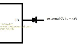 Jim VK7JH MMedit |
||||
| retepsnikrep Senior Member Joined: 31/12/2007 Location: United KingdomPosts: 134 |
Thanks for the input. I'm running 5.03.17 on a WW extreme board. I don't have anything connected to the RX pins other than a multimeter to read the voltage with reference to the pic gnd as I described. Before configuring with MBasic Com1 and 2 RX pins read zero volts. When i run this program they then read as below. OPTION EXPLICIT 'we want to ensure variables are declared explicitly OPEN "COM1:9600" AS #1 'open the first serial port with a speed of 9600 baud HLine open "COM2:10400" AS #2 'open the second serial port with a speed of 10400 baud KLine DO 'start the do loop that runs forever LOOP After configuration with the program running RX reads 3.23V or so and the 10k pulldown I tried only dropped it to 2 volts indicating 6k worth of pullup or active high drive. The pcb is one of WW extreme 144 backpack jobs.. There are no bridges that i can see and the TX pin outputs data correctly. Is the TX pin connected internally to the RX pin somehow.. Miss configured? Pullup a lot stronger than we think.. For further testing i tried a 1k resistor pulldown to gnd, this reduced the RX pin voltage to 272mv indicating a pullup strength of 11k. A 4k7 resistor to gnd reduced the voltage to 1.22V indicating approx 7.8k of pullup 10k was as i mentioned before 2v approx indicating a 6k equivalent strength pullup. The pullups are not physical resistors inside the pic so we can expect variations at different voltages. The result was the same for Com1 & Com2. However it is much stronger than expected and it breaks previous PIC comms functionality if it cannot be disabled. Stopping the running program (break) does not switch off the pullup. Only a reset of the board reverts to no voltage on the RX pins. As soon as you run the program again and initialise the com ports the pullup is activated. The RX pins do appear to work in loopback mode but are obviously taking a lot more current to be driven low. Gen1 Honda Insights. |
||||
| TassyJim Guru Joined: 07/08/2011 Location: AustraliaPosts: 6269 |
I just completed at test on a MX170 and the MZ144. In both cases I put a 1k resistor between Tx and Rx There were no problems with loss of data I measured 3.2V p-p on the Tx side and 2.92V on the Rx side. That points to about 10k internal pullup. Those figures are on the MZ144 and the MX170 were similar. Not as high as the microchip data sheets give but they have been known to be wrong. The diode I suggested above should resolve your problems. Jim VK7JH MMedit |
||||
| matherp Guru Joined: 11/12/2012 Location: United KingdomPosts: 10246 |
I don't have access to a MZ for the next 2 weeks so please can someone do the following tests: Configure a standard pin as an input with a pullup Connect a multimeter on uA range between the pin and ground. According to the MZ datasheet you should see a current flow of c40uA Open a com port and repeat the test to GND on the RX pin. Make sure there is no other connection to the test pins. Please post the results If possible also repeat for a MX processor Thanks |
||||
| retepsnikrep Senior Member Joined: 31/12/2007 Location: United KingdomPosts: 134 |
My meter on the 2ma range gives c280ua for the RX pin to GND once com1 is setup in basic. Seven times higher than your figure.. Same result for Pin1 configured with pull up as you requested. Gen1 Honda Insights. |
||||
| JohnS Guru Joined: 18/11/2011 Location: United KingdomPosts: 4038 |
Did you get c40uA before it was opened as COM1? Also, was that the MZ? If so, hopefully someone can do the MX... John |
||||
| matherp Guru Joined: 11/12/2012 Location: United KingdomPosts: 10246 |
I've re-read the datasheet and have a possible different understanding to before I think 40uA is the current the pullup can source whilst guaranteeing to still report high. This then ties in with the measured values in the range of 10-12Kohm. This then opens an interesting discussion about the MX range. The wording in the datasheet seems the same and it suggests a value of 50uA i.e. a stronger pullup. However experience seems to suggest that the MX is very much weaker than that. I'm interested to see any test reports. I can't make any changes to the MZ code for the next 2 weeks but all the above suggests that a 1K series resistor is ideal and should bring the pin well below the VIL threshold (max of 0.2 * VDD) |
||||
| retepsnikrep Senior Member Joined: 31/12/2007 Location: United KingdomPosts: 134 |
MZ2048EFH The pins initialised as DIN measured zero current to ground until pull up activated. Ditto com ports nil until activated.. Gen1 Honda Insights. |
||||
| retepsnikrep Senior Member Joined: 31/12/2007 Location: United KingdomPosts: 134 |
I agree if you have a low impedance drive. But I am working with a non rs232 12v serial line via a potential divider to bring the V swing down to the pic limits. If you choose a suitable series resistor to bring the 12v down directly to the 3.3v limit it raises the input impedance too much to fight against the internal pullup. I appreciate the input. Enjoy your holiday ;) Gen1 Honda Insights. |
||||
BobD Guru Joined: 07/12/2011 Location: AustraliaPosts: 935 |
Sometime back I bought on eBay some programmable signal converters. They were only one chip modules as I recall and you could select your signal input and output voltage levels. They sound like just what you need but I don't recall the output impedance. I don't remember the name or description. I bought them for a purpose and eventually never needed them so they disappeared into the junk box. Searching the junk box is a noisy thing and it's 5:50am here. I don't want to disturb the chief dishwasher so I'll have to wait for several hours and then I'll look. I recall that others on TBS were buying these also. Someone else may be able to help. Given the time of day in the UK, you may not get an answer before you hit the sack. |
||||
| BobD Guru Joined: 07/12/2011 Location: AustraliaPosts: 935 |
I found these level converters. They were right in the top of the junk box. Unfortunately, I can't identify them. They are almost absent of markings and I can't find any documentation. They are 15 x 12mm. See one below, a few times magnified. The four active chips are 3 terminal devices. The signals input on HV1 thru 4 and output on LV1 thru 4. HV and its GND sets the high input level and LV and its GND sets the low voltage output level. To convert from 12v to 3.3, input 12v on HV and 3.3v on LV. 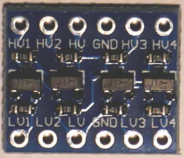 |
||||
| BobD Guru Joined: 07/12/2011 Location: AustraliaPosts: 935 |
I believe that the active device is a BSS138. I have found them on ebay as a Bi-Directional Logic Level Shifter and I used Google to search eBay. They come in 2, 4, and 8 channel modules. AdaFruit also has similar devices with a bit more info. |
||||
| skyv Newbie Joined: 14/03/2015 Location: AustraliaPosts: 14 |
Sparkfun have some details which you may find useful https://learn.sparkfun.com/tutorials/bi-directional-logic-level-converter-hookup-guide |
||||
| TassyJim Guru Joined: 07/08/2011 Location: AustraliaPosts: 6269 |
I found time to do a couple of tests. I tested on a MMX 144 pin board from WW and a 28pin backpack board from BigMick (one of the original ones with the DIL chip). I setup each mite with a resistor from the pin to ground and measured the pin terminal voltage after issuing SETPIN 80, DIN, PULLUP on the MMX and SETPIN 10, DIN, PULLUP on the MX170 28pin mite In both cases, the chosen pin was one that also gets used as a COM Rx pin. On the MX170 a SETPIN 10, DOUT gave a reading of 3.20V and the same on the MMX gave 3.12V due to the slightly different supply voltages This table shows the results for various values of load resistor ranging from zero to 33k ohms 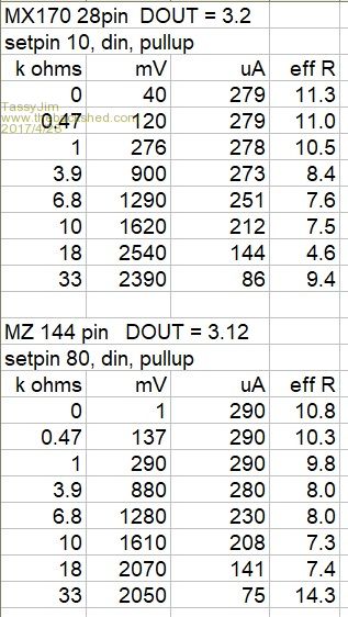 Columns are load resistance in k ohms, measured voltage pin to ground in milli-volts, measured current out of the pin in micro-amps, calculated effective internal resistance in k ohms The two graphs don't show the effective resistance. The battery on one of my meters went flat just as I finished the MX170 so no further tests were done. 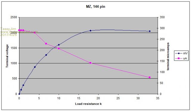 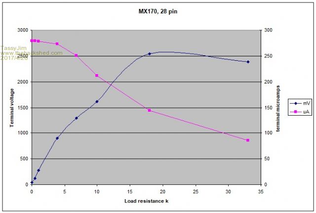 My conclusion. Both the MZ and MZ chips have very similar pullups. They both current limit to about 290 micro-amps. If you are relying on a resistor to pull the input to ground, 1k is the largest value that works reliably. Jim VK7JH MMedit |
||||
| retepsnikrep Senior Member Joined: 31/12/2007 Location: United KingdomPosts: 134 |
Thanks for the ideas. The logic level shifters look interesting. Gen1 Honda Insights. |
||||
| The Back Shed's forum code is written, and hosted, in Australia. | © JAQ Software 2025 |
