
|
|
Forum Index : Microcontroller and PC projects : MX2 board
| Author | Message | ||||
kiiid Guru Joined: 11/05/2013 Location: United KingdomPosts: 671 |
Presenting a small and simple development board for the MX270 Micromite. I designed it originally for my development needs, but made some extra number of bare boards as well. Turns out the MX270 chip did a pretty good job for me in one my more specific projects. Want to have one of these - paypal �1 plus postage (usually �1 within the UK and EU, and �1.50 for the rest of the world) to knivd at me (com). I will post to the paypal address unless otherwise specified. Happy to outsource the selling activities elsewhere in case of interest... 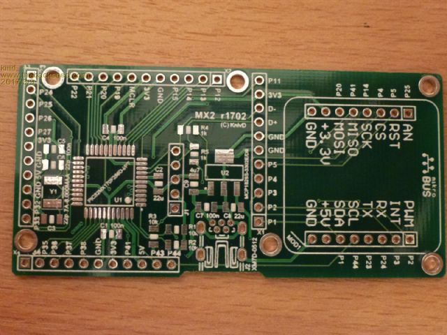 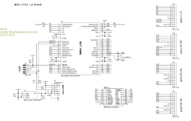 http://rittle.org -------------- |
||||
| sagt3k Guru Joined: 01/02/2015 Location: ItalyPosts: 313 |
Hi kiiid Excellent pcb, compliments !! In this post MX270-USB you have specified: 23: DIGITAL | ANALOG | COM4-RX (shared with the console) 24: DIGITAL | ANALOG | COM4-TX (shared with the console) But in this PCB I see MikroBUS RX and TX are inverted. Is this correct way ? Thanks sagt3k |
||||
| Zonker Guru Joined: 18/08/2012 Location: United StatesPosts: 761 |
Nice layout Kon..!! I love how you don't need a USB converter, and can update the firmware thru the bootloader..! Sweet... Could you post the BOM for this..? Put me down for 2... If not many available, 1 would be ok also...  I am confused with the - knivd at me (com) - part... Send funds where..? Thanks...  |
||||
| kiiid Guru Joined: 11/05/2013 Location: United KingdomPosts: 671 |
The schematic as PDF and the BOM: 2017-03-10_065606_MX2.zip To avoid confusion: knivd@me.com - this is my paypal address. The crossed lines for COM4 are correct - TX goes to RX and RX goes to TX. http://rittle.org -------------- |
||||
| kiiid Guru Joined: 11/05/2013 Location: United KingdomPosts: 671 |
Yes, that was a bug... :( I didn't have any need to use MikroBus with MX2 so that had slipped away. This is the fixed schematic. The only difference is the swapped P23 and P24 to the Click board. For Click boards using analog, I2C or SPI, the old r1702 revision is still completely fine. I will get a few revised boards r1703 made just in case. 2017-03-10_102417_MX2.zip http://rittle.org -------------- |
||||
| isochronic Guru Joined: 21/01/2012 Location: AustraliaPosts: 689 |
In general does the 44 pin include all the pins from the 28 pin 270 ? One of Lucio di Jasio's excellent books, (USB/lcd/interface etc) I think was based on the 28 pin 270, I guess a lot of the code would run on this board with a recompile (?) |
||||
