
|
|
Forum Index : Microcontroller and PC projects : Self calibration of voltage divider
| Page 1 of 2 |
|||||
| Author | Message | ||||
OA47 Guru Joined: 11/04/2012 Location: AustraliaPosts: 1050 |
I wish to be able to calibrate a Micromite voltage divider to allow for voltage drops through protection hardware and tolerances in resistor values (100K/10K). I have tested the following: Volts / Micromite Pin(x) Volts 5.0 / 0.416129 7.5 / 0.643548 10.0 / 0.870987 12.5 / 1.09667 15.0 / 1.32581 If my grey cells are correct, the gradient of the plotted points should give the correct resistor divider value: Gradient=Rise/ Run = (1.32581-0.416129)/10 = 0.09099 The offset will be where the plotted line crosses the axis ( I expect this value to be approx. 0.3 volts being the drop across the schottky polarity protection diode) Can someone help me to remember how to calculate this offset? Would I be right in assuming that the offset would be: Volts-Pin(x)/Gradient 10-0.870987/0.09099 = 0.42766 Volts Graeme |
||||
TassyJim Guru Joined: 07/08/2011 Location: AustraliaPosts: 6537 |
I cheat and put the readings into an excel spreadsheet then add a trendline to the graph 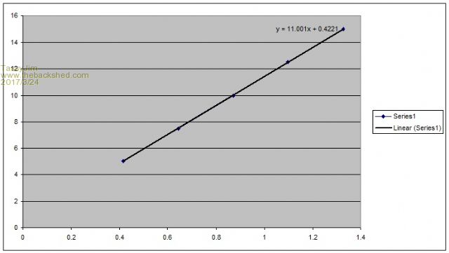 A very linear set of data points. The formula is V = x * 11.001 + 0.4221 In your setup, the voltage drop across the diode is 0.4221V Jim VK7JH MMedit |
||||
| OA47 Guru Joined: 11/04/2012 Location: AustraliaPosts: 1050 |
Thanks Jim, I have a stable 5.0v and a 12.0v supply rails in the project so I can use those to set two reference points and calculate the values needed to keep accuracy. Graeme |
||||
| OA47 Guru Joined: 11/04/2012 Location: AustraliaPosts: 1050 |
I must be missing something. The results I get from my code don't seem to be consistent or accurate. Is there a factor that I am missing such as extra current draw on the analogue pin with the different voltages? Here is the code snippet I am using Pin(17)=1 'APPLY 5.0V TO PIN 23 VIA 4066 V1=Pin(23) 'THIS VALUE SHOULD BE APPROX 0.41 FOR 5V For Flash = 1 To 2: Pulse 15,BLNK*4 : Pause 250 : Next Flash ' Flash GREEN X2 Print "V1 MEASURED AT";V1 Pin(18)=1 'APPLY 12.0V TO PIN 23 VIA 4066 V2=Pin(23) 'THIS VALUE SHOULD BE APPROX 1.16 FOR 12V For Flash = 1 To 2: Pulse 15,BLNK*4 : Pause 250 : Next Flash ' Flash GREEN X2 Print "V2 MEASURED AT";V2 CAL= 7/(V2-V1) 'THIS VALUE SHOULD BE APPROX 11.0 (100K/10K) DIODE=12-(V2*CAL) 'THIS VALUE SHOULD BE APPROX 0.4 FOR SCHOTTKY DIODE Print "CAL=";CAL;" DIODE=";DIODE;" SAVE TO NVM ?"; Input K$ If K$="Y" Or K$="y" Then VAR SAVE CAL, DIODE |
||||
| flip Senior Member Joined: 18/07/2016 Location: AustraliaPosts: 124 |
Assume you're powering 4066 off 5V and using an external pull-up resistor to 5V on Pin 17 to get a definite High? Not sure of the circuit, or what results you got, could it be the 4066 on resistance? book says its typically 270 ohms @ 5V but could be up to 2500 ohms. But admittedly you would only expect a small error from this (depending what part of the divider you're switching... Have you actually measured the voltages with a voltmeter? Phil |
||||
| TassyJim Guru Joined: 07/08/2011 Location: AustraliaPosts: 6537 |
I think I understand now what you are trying to do. I assume the initial set of readings you posted were done with a multimeter and not the micromite. I was surprised by the very liner graph they produced. Can you do it again and use the micromite as well as a multimeter to give a comparison? I think your resistor values are too high. I use 10k and 2.7k for a max 15.5V input. That uses more of the 3.3V range to give better resolution and the lower values help negate the input impedance. With all things equal, we are still only using a 10 bit ADC converter. This results in about 3mV resolution so you need to expand the working range as much as possible. The micromite takes 10 readings internally for one read so that improves the resolution a bit. On my solar 12V supply I ended up taking 100 readings about 8mS apart and averaging them to get my battery voltage. The high number of reads were required because the solar regulator has a very slow PWM controller and I need the long averaging time to smooth out the readings. As you are flashing a LED with each read, you could easily add a few more reads without taking up any more time. The stability of the 3.3V supply is also important so anytime I want better readings, I use a 2.5V reference and use it to calibrate the 3.3V. Jim VK7JH MMedit |
||||
| OA47 Guru Joined: 11/04/2012 Location: AustraliaPosts: 1050 |
@ Jim, the first set of figures I posted were read from the multimeter and the result of the micromite pin(x) value. The reason I chose the higher values for the voltage divider as the power requirements are very stringent. I think you have directed me to the problem with the stability of the micromite. The software has it sleeping for 2 secs and waking for a measurement for a couple of milliseconds and I don't think that there is enough stabilisation time. @ Flip, I was confirming the voltage on the micromite side of the 4066 with a multimeter. Back to the drawing board :-( Graeme |
||||
| TassyJim Guru Joined: 07/08/2011 Location: AustraliaPosts: 6537 |
To keep load down but improve resolution, try 10k and 39k resistors or 15k and 56k I would prefer the lower value resistors but the high values would be an interesting experiment. Jim VK7JH MMedit |
||||
| OA47 Guru Joined: 11/04/2012 Location: AustraliaPosts: 1050 |
Ok, so I decided to bring the micromites voltage up a bit by doubling up on the 100K resistor (they are SMD) making 10k/50k divider and taking 3 readings: 6.00V 0.863441 10.00V 1.52581 14.00V 2.17742 The Micromite calculated the gradient of 6.08838 and offset of 0.710313 using the 6v and 14v values to get the gradient & 10V value to calculate the offset. Loading the figures into EXCEL: 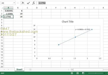 The equation is not far out but when I take further measurements using these figures at 6.00v input I get 6.48445 and 12.00v I get 12.4812. I still cant see why there is a variation during normal program execution and the calibration area of the code. Graeme |
||||
| isochronic Guru Joined: 21/01/2012 Location: AustraliaPosts: 689 |
4066 ??? circuit ???? "micromite voltage divider" ???? |
||||
| TassyJim Guru Joined: 07/08/2011 Location: AustraliaPosts: 6537 |
0.73 seems high for a schottky diode. Perhaps there is not enough current through the diode to give a consistent voltage drop. With the second set of reading both showing high by a similar amount, it does look like a shift in the diode drop. It also could be temperature related. If it's any consolation, I spent 2 weeks trying to get a reliable zero current reading from some ACS712 sensors. It feels good when you finally get a win. Jim VK7JH MMedit |
||||
| OA47 Guru Joined: 11/04/2012 Location: AustraliaPosts: 1050 |
@ Jim, the particular circuit I got those figures from had a SMD equivalent of a 1N4001 diode that I measured @0.59v drop using the diode test setting on the multi-meter. @ Chronic, for the reasons of test, I gained these figures using the minimum of components. I scratched together a circuit, hope it helps. 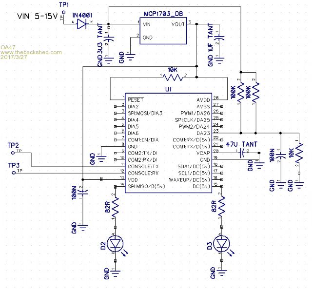 |
||||
| flip Senior Member Joined: 18/07/2016 Location: AustraliaPosts: 124 |
For 6V input should read exactly 1/6 of 6V = 1V. 10/(10+50) = 1/6. If you're using it to work out voltage at TP1, maybe better putting top of divider to TP1, otherwise, with circuit as-is you could get variation of maybe .3V depending on the variation in current load during sleep. Regards, Phil |
||||
disco4now Guru Joined: 18/12/2014 Location: AustraliaPosts: 1127 |
Graeme, I used a 47K/10K divider for a dual battery monitor way back. I seem to remember a significant change in the measured voltage by adding extra capacitance across the VCC rail. Just added 10uF from memory. I think it made 200mV difference in the reading. Worth a try. Regards Gerry F4 H7FotSF4xGT |
||||
| isochronic Guru Joined: 21/01/2012 Location: AustraliaPosts: 689 |
[I wish I could produce schematics that fast   !!] !!]I think the A/D supply (which is also the ref voltage) is getting hash from the regulator, try a 0.1 uF bypass (ed -ceramic). There is a Silicon Chip project, I forget whether it was a voltage reference or power monitor, that had a similar set up and problem, fixed OK. There are a number of other things but that would be the most citical I think. Also diode voltage drop alters with current to some extent, even for schottkys. |
||||
| Phil23 Guru Joined: 27/03/2016 Location: AustraliaPosts: 1667 |
Ugh, Am I in for some grief & hair tearing, with what I mentioned in my other post? Just want to monitor around 3 amps (240V). Can you offer a suggestion of what worked for you if it's relevant to my case. Thanks Phil. |
||||
| TassyJim Guru Joined: 07/08/2011 Location: AustraliaPosts: 6537 |
For 3A AC, I would use a current transformer and rectifier then use an analogue input pin. I like to see the isolation. Jim VK7JH MMedit |
||||
| Phil23 Guru Joined: 27/03/2016 Location: AustraliaPosts: 1667 |
Same... So I had also bought a couple of these... Haven't yet decided which devices to actually use. 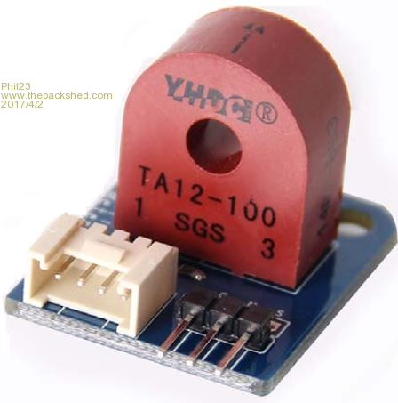 1000:1 ratio & 200ohm shunt. Says 5v out @ 5A which will be AC, but not sure how to deal with the 0.7? of 1.4? lost in rectification. That would mean losing readings under 0.7 amps with out some other solution. Very rusty on this front.... Phil. |
||||
| TassyJim Guru Joined: 07/08/2011 Location: AustraliaPosts: 6537 |
Do a google search for "precision rectifier" There are simple one op-amp circuits and a few IC's that are designed for the task. AS well as rectifying, you need to decide the time constant for the output filter - that determines haw quickly the circuit responds to changes in current. Jim VK7JH MMedit |
||||
| OA47 Guru Joined: 11/04/2012 Location: AustraliaPosts: 1050 |
Thankyou for all the replies shedders. Sorry I have not been able to get back sooner but I have been away and I can read posts on my phone but it is difficult to prepare posts which can be easily done on the PC. Getting back to my original conundrum I may have been a bit unclear with my current concerns (no pun intended). I have earlier posted a cut down circuit and I have cut down the code by making it call for manual voltage measurements to try and work out what is going on. Here is the code for the calibration sub: Sub CALIBRATION Input "DOES THIS UNIT NEED THE PULLUP RESISTORS ACTIVATED ON UNUSED INPUTS?";K$ If K$="Y" Or K$="y" Then PLUP=1 NEED_PULLUPS EndIf Input "SET OPERATIONAL VOLTS TO 6.0v & PRESS ENTER WHEN SET";K$ V1=Pin(23) 'THIS VALUE SHOULD BE APPROX 0.86 FOR 6V For Flash = 1 To 2: Pulse 15,BLNK*4 : Pause 250 : Next Flash ' Flash GREEN X2 Print "V1 MEASURED AT";V1 Input "SET OPERATIONAL VOLTS TO 10.0v & PRESS ENTER WHEN SET";K$ V2=Pin(23) 'THIS VALUE SHOULD BE APPROX 1.53 FOR 10V For Flash = 1 To 2: Pulse 15,BLNK*4 : Pause 250 : Next Flash ' Flash GREEN X2 Print "V2 MEASURED AT";V2 Input "SET OPERATIONAL VOLTS TO 14.0v & PRESS ENTER WHEN SET";K$ V3=Pin(23) 'THIS VALUE SHOULD BE APPROX 2.16 FOR 14V For Flash = 1 To 2: Pulse 15,BLNK*4 : Pause 250 : Next Flash ' Flash GREEN X2 Print "V3 MEASURED AT";V3 CAL= 8/(V3-V1) 'THIS VALUE SHOULD BE APPROX 6.0 (50K/10K) DIODE=10-(V2*CAL) 'THIS VALUE SHOULD BE APPROX 0.4 FOR SCHOTTKY DIODE Print "CAL=";CAL;" DIODE=";DIODE;" SAVE TO NVM ?"; Input K$ If K$="Y" Or K$="y" Then VAR SAVE PLUP, CAL, DIODE End Sub As per my earlier post I received the following samples : 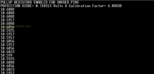 The issue is that the future voltage readouts made every two seconds after for a 10.00 Volt input are consistently approx. 0.6 Volts out. I am at a loss to figure out why. Graeme |
||||
| Page 1 of 2 |
|||||
| The Back Shed's forum code is written, and hosted, in Australia. | © JAQ Software 2026 |
