
|
|
Forum Index : Microcontroller and PC projects : Welder Control
| Author | Message | ||||
| Zonker Guru Joined: 18/08/2012 Location: United StatesPosts: 761 |
Good evening Gents Just wanted to get out an update on a simple Welder Controller my buddy Ed Hase wanted to spin up. Since it doesn't need a lot of I/O, we decided on the MX170 28 pinner. The device is meant as a replacement for a "failed" wire speed motor control board in the "low-end" welders. Ed said there seems to be a need for replacements, as the original PCBA's are expensive to replace or, worse yet, not available. We found a few suppliers that have created replacement motor control designs, but the prices were "striking"... If you have a cheap welder, the replacement control could end up costing you almost as much as a new welder unit..! Yikes... So, we talked about creating a new version of a control that would add value and new features to any welder unit, and possibly worth the cash being invested. Besides controlling the wire feed speed motor, we added another output to control the purge gas. Adding some simple timers, we created a control with three "modes" of operation. Manual, Spot and Stich. At first, we started out by connecting up simple pots as a user interface to control the actions of the board's six inputs, WireSpeed, Gas Delay, Spot time, Stich On/Off times as well as an ON-OFF-ON Switch for the mode select. This seemed to work OK, but was hard to work with in practice. And just think, anyone could walk up to your welder, twist a few knobs just to piss someone off, wasting your time getting things "dialed in" again... (and I thought this would be a simple, fast project)...  So, since I was thinking about trying to reduce cost and was having a hard time finding the correct pots I wanted, I bit the bullet and decided to replace them with one simple encoder control knob with the push button built in. Toss in an ILI9341 SPI display board on top, and you now have a better-protected user interface. And, oh yes, we can now add in "setup memories" so the end user can store his/her fav's too.! Note: the touch part of the display is hooked up, but not used... 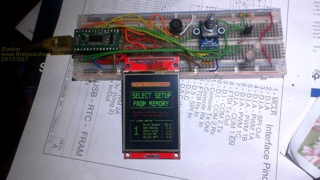 The prototype setup still fits on the standard size vector board. You just have to watch out that the "white kitty" doesn't keep pulling the wires off of it..! Since I allready had the basic (pun entended) program written to control the "actions", I just had to recreate a GUI for the end user. My first thoughts... K.I.S.S. method... 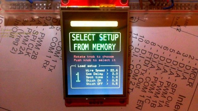 So, when you turn things on, the user is presented with the setup load screen. there are nine different "slots" the end user gets for setup memory. Using the knob, you can cycle through them, with the display showing the values stored for each of the setting's. Setups are stored in the VAR SAVE flash area using a 255 byte array. I also stored a few fonts in the library area to make better looking layout on the display. Now, this is not the "fancy" 470 motor, so doing screen layout is a bit more time consuming, but I think you can do some really good stuff with the tools included on the "babby- mite".... Pin count and cost keeped within buget... 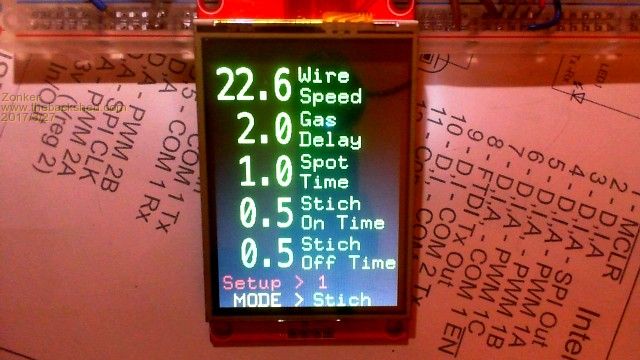 After the five-second setup selection timer expires, or the user selects one of the settings previously saved, you are presented with the main operations screen. The "trigger" input will now be active, allowing welder operations to commence. If the end user wants to, pressing the select button on the encoder, disables welder operation, enters setup "edit" mode, allowing changes to the current set of values being displayed so the settings can be "tweaked". When done fussing around, pressing down the select button for over one second, updates the settings in flash for later. So, I think I smell a fresh PCBA coming on for this one... Anyway... Nuff babling for now... Time for some rack... 4:30AM hits hard on Monday's |
||||
TassyJim Guru Joined: 07/08/2011 Location: AustraliaPosts: 5914 |
Looks good. I like the combination of LCD and encoder. The encoders are better suited to typical workshop paws. Jim VK7JH MMedit MMBasic Help |
||||
| paceman Guru Joined: 07/10/2011 Location: AustraliaPosts: 1328 |
Zonker - what manufacturer/model encoder did you use and what did you use to debounce it (hardware &/or software) - and how effective is it? Greg |
||||
| Zonker Guru Joined: 18/08/2012 Location: United StatesPosts: 761 |
Hey, Gents... Just an update. I got the "Proposed" Schematic done, working on the layout... 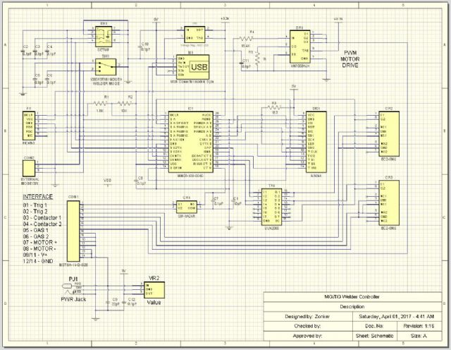 Probably small changes yet. Maybe a blocking diode on power in... |
||||
