
|
|
Forum Index : Microcontroller and PC projects : Boat Computer - NEO-6M GPS
| Author | Message | ||||
| Trevorc Newbie Joined: 26/02/2017 Location: United KingdomPosts: 22 |
Hi All, I need some help with the Boat Computer. I am using a Neo-6m which works well in direct serial mode and with the Neo U-Center program. I have made up a board in exactly the same way as an LCD Backpack. But it will not get past the GPS Moodule Not Found bit. I have been able to run it in Demo Mode and all is well. I have tried another chip programmed with the the full hex file and still no different. Has anybody else had this problem, or any suggestions on what may be wrong. Hope someone can help I have spent days trying different ideas. |
||||
TassyJim Guru Joined: 07/08/2011 Location: AustraliaPosts: 6504 |
If the GPS works in direct serial mode, what settings are you using to connect to it? Can you supply an example of it's output? The boat computer code is testing various baud rates as well as inverted so it should find your GPS if it's a 'normal baud rate. The code then looks for "$GP" in the received string. Can you run the board with a terminal attached so we can do some debugging? This extract should print lots of garbage on the terminal screen during testing and eventually have something useful If you are sure about the baud rate, you can make it the first one in the array. Jim VK7JH MMedit |
||||
| Trevorc Newbie Joined: 26/02/2017 Location: United KingdomPosts: 22 |
Hello Jim, Thank you for your kind interest. I have spent all day trying to get this working, so I have only just received your reply. By a console, do you mean something like the ASCII Video Terminal or just my PC. I have made the Video Terminal and tested it but have not got it set up with a monitor at the moment. I will have to check out your ideas tomorrow. But basicaly if I connect the GPS using a normal CP2102 usb serial adaptor at 9600 , I get a full listing of all the satelites found, within seconds. If I use the U-Blox u-center program, I get a full map of all satelites found, usually about 7 of them. I have made my circuit up on a piece of veroboard and have checked all connections thoroughly, even so, I have ordered PCB's for the LCD backpack and I hope that this will solve the problem. I will try your mini program tomorrow and let you know how I get on. Many thanks and kind regards, Trevor. |
||||
| WhiteWizzard Guru Joined: 05/04/2013 Location: United KingdomPosts: 2962 |
Hi Trevor, Following on from our phonecall yesterday, TassyJim has posted a great example of a 'three line program' (ok - maybe a few more than three lines) to try things out. You have confirmed above that the GPS module correctly 'kicks out' data at 9600 baud so I recommend that you simply replace Jim's first line with: DIM string baud(0)="9600" and you should then get some response. IF not, then there is likely to be a 'hardware' issue with your circuit. I possibly misunderstood you yesterday in that I assumed you had built your circuit on a BackPack PCB - but above you mention 'veroboard'. Can I suggest you post a close-up photo of your circuit (if possible). If you look at the 'facts' - you have eliminated a GPS issue as it works with your USB module into the PC; and the MMBASIC code is known to work (especially if you fix it at the correct baud rate). So this leaves just the 'other' hardware as the issue  Do keep us updated with progress as I am curious as to what exactly is the 'issue'  WW |
||||
| TassyJim Guru Joined: 07/08/2011 Location: AustraliaPosts: 6504 |
By a console, I do mean your PC, but any terminal that talks to the micromite would do. If the GPS works connected to a CP2102 usb serial adaptor at 9600, I suggest that you might have the Rx and Tx lines swapped. This program keeps trying at 9600 and 9600 inverted until you give up or it succeeds. You can test connections while it's running. Something should print out each second, even with no GPS attached. Jim VK7JH MMedit |
||||
| Trevorc Newbie Joined: 26/02/2017 Location: United KingdomPosts: 22 |
Hello Jim and WhiteWizzard, Thank you so much for your contributions. I have tried the mini program and as Jim said, there was a lot of rubbish with no sensible phrases. Over the weekend, I have checked and treble checked my Veroboard layout, connections, changed the capacitors and cooked the solder joints. As this brought no answer, I took a look at the serial pins from the GPS unit with my old scope. The signal from the gps is stable and as I would expect. I was surprised that the Micromite pins (not connected to anything), were flip flopping from high to low and if I connected the GPS, the GPS signal was taken to about half volts when the Micromite pin was low. I am not sure that this is how it should be or not. Also I have changed the Micromite chip with no difference. The only thing that worries me now is that on checking the power supply I am using, it is rated at 350ma not the 500ma that is recommeded. My thoughts on this are as the circuit only draws 130ma and the voltage sits at 3.25v, I do not think this matters. I do not have a power supply larger than the 350ma, but I will be gratefull for your comments on that. I feel that my way forward is to wait untill I get the PCBs I have ordered and hope that that works. |
||||
| WhiteWizzard Guru Joined: 05/04/2013 Location: United KingdomPosts: 2962 |
HI Trevor, Few things to feedback to you: A MicroMite will run fine even at 2.7v so no issues there. A 28 pinner will typically draw around 30mA. Some GPS modules will draw a considerable amount of current. Normally this should be below 100mA BUT for some 'cheaper GPS modules' (i.e. eBay 'specials'), then I have seen in excess of 400mA. I assume that when you had your GPS powered and working with a direct connection to your USB-to-UART module, then you are using the same PSU with your 'MicroMite' setup? I very much doubt the extra 30mA required by the MicroMite will make it suddenly stop working. Can you confirm you have vCap (in affect) across Pins 19 & 20. This needs to be somewhere between 10uF and 47uF (inclusive) and NOT an electrolytic. Use a Tantalum (if thru-hole) or Ceramic (MLCC) if SMD. The fact you are getting 'rubbish' back can be considered as 'good'. Was the rubbish coming back at regular intervals? If so, then sounds like a baud rate issue. If not - then difficult to resolve apart from checking things like the points mentioned above. How long do you have to wait for your PCBs? I can always send you a BackPack PCB if that helps . . . WW |
||||
| matherp Guru Joined: 11/12/2012 Location: United KingdomPosts: 11143 |
This really makes it sound like you have the connections reversed. It must be GPS-TX to Micromite-RX and visa-versa. You should never see "half volts" unless you have two outputs driving against each other |
||||
| Trevorc Newbie Joined: 26/02/2017 Location: United KingdomPosts: 22 |
Hello WhiteWizzard, Hey, that was quick. Just to go through your list:- The GPS module I am using draws between 10 an 20ma at startup and goes down to less than 10ma when it has a fix. I have powered the GPS both from USB and the 3.3v 350ma supply with no problems I have a vCap on pins 19(-) and 20(+) it is a new tant 47mfd. I call them "gonks" The rubbish, was coming back at regular intervals. If it is a baud rate issue, is it an idea for me to experiment with slightly differenf rates either side of 9600. Say adding or subtracting 50 each time. While I remember, I also tried using COM2, but, it just said that COM2 was allready in use. The PCBs I have ordered have been despatched, they should come in the next 2 to 4 weeks. I would like one earlier, can you let me know what to do to order one. Many thanks Trevor. |
||||
| Trevorc Newbie Joined: 26/02/2017 Location: United KingdomPosts: 22 |
Hello Matherp, Sorry, I missed your posting in my eagerness to reply to WhiteWizzard. That was my thinking as well. But the GPS TX is connected to Pin 22(Com1 Receive) and the RX connected to Pin 21(Com1 Transmit). I know there is something daft going on and although the circuit is relatively simple I cannot find a fault. I am hoping a proper PCB will sort it out. Many thanks for your imput. Trevor. |
||||
| TassyJim Guru Joined: 07/08/2011 Location: AustraliaPosts: 6504 |
First silly question. Do you have the grounds connected? If you can see the output of the GPS changing when you plug it into the 'mite, can you see what happens when you plug it in with the 'mite chip unplugged. If the GPS output still dies without the 'mite plugged in, you have a problem with your board - a short to ground etc. Your description does point to connecting to the wrong pin. Jim VK7JH MMedit |
||||
| Trevorc Newbie Joined: 26/02/2017 Location: United KingdomPosts: 22 |
Hello Jim, Not silly questions. The grounds are all connected as per the Boat Computer Schematic. If I take out the chip, the signal is at full volts with no changes. I have tried reversing the leads on pin 21,22, it makes no difference. I have spent the morning checking my board for shorts to the extent of measuring each pin with the others an can find no fault. I am just hoping that when I get the proper PCB, I will be able to construct a working one. Thanks for your interest. Trevor. |
||||
GoodToGo! Senior Member Joined: 23/04/2017 Location: AustraliaPosts: 188 |
@TrevorC, I've got a Neo-6m module (GY-GPS6MV2) running happily on my MM+ LCD backpack. Default is 9600 baud. Is it possible that by connecting it to the U-Blox program that it's changed some of the modules default settings? Is the module definitely using the serial outputs and not one of the others? (eg. USB outputs) Do you have a photo of the module and setup you are using? Cheers, GTG!  ...... Don't worry mate, it'll be GoodToGo! |
||||
| Trevorc Newbie Joined: 26/02/2017 Location: United KingdomPosts: 22 |
Hello GoodToGo, Thanks for your contribution. I have attached some photos, though I don't think it will help you much. Not sure what you mean about U-Blox changing settings as it only a serial(TTL) device. Hope you can spot something I havn't. Kind regards, Trevor Sorry, I will have to do the photos later. They are too big to send. |
||||
| Trevorc Newbie Joined: 26/02/2017 Location: United KingdomPosts: 22 |
Hi again GoodToGo, Hopefully, the photos are attached. Sorry, I have not posted pictures on this forum before. Trevor 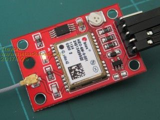 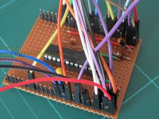 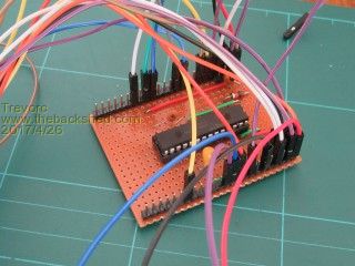 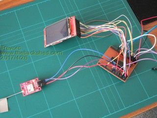 |
||||
| GoodToGo! Senior Member Joined: 23/04/2017 Location: AustraliaPosts: 188 |
Hi Trevor, Do you a photo of the bottom of the veroboard? Cheers, GTG! ...... Don't worry mate, it'll be GoodToGo! |
||||
| Trevorc Newbie Joined: 26/02/2017 Location: United KingdomPosts: 22 |
Hi GTG, I didn't but I have now. Here it is. Trevor  |
||||
| GoodToGo! Senior Member Joined: 23/04/2017 Location: AustraliaPosts: 188 |
Hi Trevor, I see your gps module is slightly different to mine and has 4.7k series resistors inline with the Tx and Rx lines. I'm betting that's the issue. Try shorting them. The module I'm using is this one ebay link You can see there are no resistors.... Let us know how you go. Cheers, GTG! ...... Don't worry mate, it'll be GoodToGo! |
||||
| Trevorc Newbie Joined: 26/02/2017 Location: United KingdomPosts: 22 |
Hello GTG, Well spotted. I have shorted the resistors as suggested and guess what, IT WORKS. HOORAY. A big thank you to WhiteWizzard, Jim and yourself of course. I may not have found that in a month of Sundays. But I did feel that there was some problem with the levels. Thanks again. Trevor. |
||||
| The Back Shed's forum code is written, and hosted, in Australia. | © JAQ Software 2026 |
