
|
|
Forum Index : Microcontroller and PC projects : ILI9341 Backlight circuit
| Author | Message | ||||
OA47 Guru Joined: 11/04/2012 Location: AustraliaPosts: 1044 |
I am having issues with a simple backlight circuit with the ILI9341. I had assumed that the internal circuitry of the LCD module was just a pin to resistor to the backlight LED to negative but there seems to be something else happening. I have used a BC338 transistor with base to pin 24 via a 1K resistor, the collector to 5V supply via a 82 ohm resistor and the emitter connected to the LED pin (8). This circuit works until the display is addressed then stops. I can operate the backlight using only pin 8 and 2 by pin(24)=1 and off with pin(24)=0. When I operate with the LCD fully connected I cant operate the backlight yet if I short emitter to collector of the BC338 the backlight works.  HELP please Graeme |
||||
| matherp Guru Joined: 11/12/2012 Location: United KingdomPosts: 11109 |
The simplest guaranteed solution is a npn transistor (or n-channel mosfet) driving a PNP transistor (or p-channel mosfet). See the this circuit for how I do it on all my boards |
||||
| OA47 Guru Joined: 11/04/2012 Location: AustraliaPosts: 1044 |
Thanks Peter for the reply. As with other projects I have wanted backlight variation of brightness here all I want is to disconnect the backlight on conditions to conserve power. Graeme |
||||
| robert.rozee Guru Joined: 31/12/2012 Location: New ZealandPosts: 2498 |
peter: in your schematic, it looks like you have the collector of the (NPN) BC817 connected to ground, while the emitter is connected to 5v via a resistor. the pins are reversed to what they should be - i assume the diagram is wrong while the PCB layout is correct (emitter connected to ground). cheers, rob :-) |
||||
bigmik Guru Joined: 20/06/2011 Location: AustraliaPosts: 2979 |
GDay Graeme, There was an extensive discussion on this 12-18 months ago. It really is not easy to drive a 3v3 powered LED circuit fully using a 3v3 high level drive) The circuit below is what I use for my BackPack 170 and does work very well.. The resistor values are pretty tight so you may not get a good result by changing them but it has always worked well using the values shown. I tried a BC558 transistor but could not get full brightness). You can use PWM to set any value brightness between OFF and ON or simply any 3v3 output pin so that LOW=OFF and HI=ON. 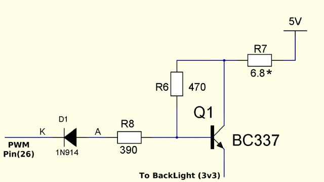 Kind Regards, Mick Mick's uMite Stuff can be found >>> HERE (Kindly hosted by Dontronics) <<< |
||||
| OA47 Guru Joined: 11/04/2012 Location: AustraliaPosts: 1044 |
Thanks Mick, I do remember your exhaustive efforts some time ago when you were developing the backpack. I was again looking for a short cut to turn the backlight off with the minimum of components and again it brought me unstuck. I will leave the mysteries of the backlight circuitry for now and use you tried and tested method. Regards Graeme |
||||
| bigmik Guru Joined: 20/06/2011 Location: AustraliaPosts: 2979 |
Graeme, The secret to the above circuit is the blocking diode, this allows the transistor bias resistors to pull the base of the BC337 to around 3v8 or slightly higher to turn the transistor on without causing damage to the 3v3 level PIC pin.. The backlight will draw about 60-70mA at around 3v3 when on. In any case it just works.. All my backlight boards now use this circuit.. Kind Regards, Mick Mick's uMite Stuff can be found >>> HERE (Kindly hosted by Dontronics) <<< |
||||
Grogster Admin Group Joined: 31/12/2012 Location: New ZealandPosts: 9919 |
I like to use the NPN transistor driving a P-MOSFET concept to drive the backlight on any LCD where I need to turn the backlight off and on. I can't remember why, but standard transistor arrangements did not work for me - might have been the way I was doing it at the time.  Smoke makes things work. When the smoke gets out, it stops! |
||||
| robert.rozee Guru Joined: 31/12/2012 Location: New ZealandPosts: 2498 |
most likely the base resistor for the PNP transistor was too high; if your backlighting draws 100mA from the 5v rail, and your PNP transistor has a gain of 100, then you'd need a base current of 1mA. this translates to a base resistor of only a few k's (3k3 would be a safe bet, bearing in mind your losing 0.6v in Vbe of the PNP and possibly a little bit due to Vce of the NPN). and you'd want the base to emitter resistor on the PNP transistor to be quite high, perhaps 10k or more. the base resistor for the NPN could be fairly high, 22k would be a safe choice. folks often don't realize that when switching even a moderate load, you can need a fair base current to fully saturate a transistor. you also need to be sure that you are overcoming any base capacitance (in both the NPN and PNP transistors) if using PWM. cheers, rob :-) |
||||
| OA47 Guru Joined: 11/04/2012 Location: AustraliaPosts: 1044 |
This was the basic of my first post. I could get the backlight to turn on and off via a pin but as soon as the ILI9341 was addressed this function would not continue. As Bigmik mentioned it seems there is interaction with the basic circuit that biasses the transistor differently. Graeme |
||||
| The Back Shed's forum code is written, and hosted, in Australia. | © JAQ Software 2026 |
