
|
|
Forum Index : Microcontroller and PC projects : Microbridge Won’t Flash.
| Page 1 of 2 |
|||||
| Author | Message | ||||
| Phil23 Guru Joined: 27/03/2016 Location: AustraliaPosts: 1667 |
Just attempted to upgrade a few of my devices to 5.04.05 with the Microbridge Y not having any luck. Sometimes I don't get the LED to light when I press the program button, seems a bit timing based maybe. But when I do get it to come on the program reports target not found. First devices I was trying were 28 pin backpacks & when I changes back to the Nano based programmer they both flashed ok. Any ideas anyone? Phil. 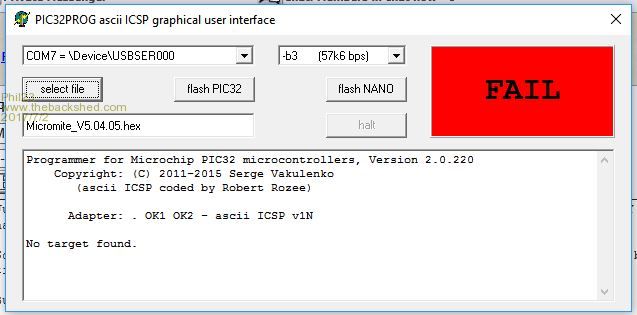 |
||||
| Geoffg Guru Joined: 06/06/2011 Location: AustraliaPosts: 3351 |
The program button works fine on the prototypes. You might have a power supply issue. Regarding the program fail, did you close the terminal emulator connected to the Microbridge? Geoff Geoff Graham - http://geoffg.net |
||||
| Phil23 Guru Joined: 27/03/2016 Location: AustraliaPosts: 1667 |
No other terminal software connected. Also no other connection to the backpack other than the M/B. IE, I don't have a power connection. Assuming it goes via the 6 ICSP connector like the Nano one does. The LED goes off immediately after the software identifies the programmer. On Win10 & tried with the native driver & the one on Microchips site. (Not expecting that to change the issue). Noted now also that the mode button appears reliable on USB/2 & maybe not quite as on USB/3 ports. Phil |
||||
| Phil23 Guru Joined: 27/03/2016 Location: AustraliaPosts: 1667 |
Power seems to be the issue. Same failure with an E64 with just the M/B. But if I power the E64 via a different USB port it flashes fine. And way faster than the Nano. 2:06 Vs 52 seconds. Suspect it might be something to do with Toshiba's power management. Phil |
||||
| Geoffg Guru Joined: 06/06/2011 Location: AustraliaPosts: 3351 |
Thank Peter Mather and Robert Rozee for that, I just documented their work. Geoff Geoff Graham - http://geoffg.net |
||||
| WhiteWizzard Guru Joined: 05/04/2013 Location: United KingdomPosts: 2962 |
Regarding the standalone MicroBridge (MB) module: Not sure if anyone else seeing this but if the MB's serial Rx pin is not connected to anything, and the USB is attached to a PC, then the button seems to be very unresponsive (i.e. LED not lighting up) Sometimes, when bringing my hand near to the MB PCB, it causes the LED to flash at about 3Hz. When (or rather IF) I get the LED to turn on when the button is pressed, then I get inconsistent 'success' with a 'programming session'. My current solution is to simply short out the Rx & Tx pins and then power up the MB, then the button responds 100% of the time as it should. Also, subsequent 'programming sessions' work without issue. NOTE: This is with a PIC16F1454. I have not tried with a 1455 yet to see if this is different! Its as if the Rx pin should not be 'floating'. The MMX144, E28, and BackPack v2 (which all incorporate a MB onboard) do not have the above issue because the MB's Rx pin is not floating. To be clear, the above 'issue' is when using a laptop powered via a PSU (i.e. not on battery). Could be a ground issue - will look into this more. Be interested if anyone else seeing this issue - and if so, does a jumper link on Rx to Tx 'resolve' the issue? WW |
||||
CircuitGizmos Guru Joined: 08/09/2011 Location: United StatesPosts: 1427 |
I make this: 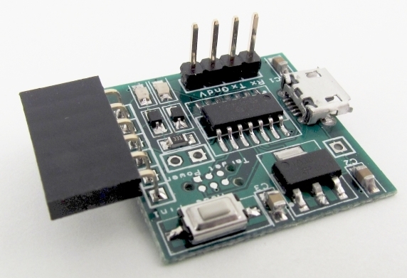 and have not had any issues. Micromites and Maximites! - Beginning Maximite |
||||
| robert.rozee Guru Joined: 31/12/2012 Location: New ZealandPosts: 2498 |
try adding a 10k pullup to the switch and see if this helps. cheers, rob :-) |
||||
| Phil23 Guru Joined: 27/03/2016 Location: AustraliaPosts: 1667 |
|
||||
| robert.rozee Guru Joined: 31/12/2012 Location: New ZealandPosts: 2498 |
a 10k resistor soldered between pins 1 and 4 of the 1455. cheers, rob :-) |
||||
| Geoffg Guru Joined: 06/06/2011 Location: AustraliaPosts: 3351 |
I thought that an internal pullup was configured on pin 4. Is that not right? Peter? Geoff Geoff Graham - http://geoffg.net |
||||
| robert.rozee Guru Joined: 31/12/2012 Location: New ZealandPosts: 2498 |
on the E-28 i found it necessary to add the 10k pullup resistor to prevent erratic behaviour similar to that described. if (for whatever reason) the select input is detected by the firmware as being high for more than 2 seconds, the 1455 firmware will exit ascii ICSP mode. yes, an internal pullup is configured, at the time i double-checked this was the case with peter. but bear in mind that pin 4 has the additional role of Vpp, where it needs to be able to have 13v fed into it to enter hv programming mode, so may by design behave differently to other pins. cheers, rob :-) |
||||
| Phil23 Guru Joined: 27/03/2016 Location: AustraliaPosts: 1667 |
Just tried WW's suggestion, Bridging Tx & Rx pins, & the button responds 100% also; but I still get target not found when connected to a Backpack. I can get it to flash successfully though if I take a jumper lead from the 3.3V on Con2 to the 3.3V pin on the LCD Backpack. Will try the 10k pull-up a bit later after work, but it seems that that power is not getting to the ICSP via Con3. Phil. |
||||
| Phil23 Guru Joined: 27/03/2016 Location: AustraliaPosts: 1667 |
So after a close look at the diagrams in Silicon Chip, (and reading things...), I see there is no power to Pin 3 of the ICSP connector; that's what was causing me to get no Target Found. Must say I overlooked that & presumed power was present, & it behaved like the Arduino Nano programmer & powered the Pic from via the ICSP connector. Also the photo of it alone plugged in to the backpack above the PicKit3, added to that assumption. So is it fair enough to hardwire the 3.3V to Pin 2 on the ICSP? Or is that going to give me other limitations on different devices. Thanks Phil. |
||||
| WhiteWizzard Guru Joined: 05/04/2013 Location: United KingdomPosts: 2962 |
Hi Phil, That will work BUT beware of a couple of things: 1> If flashing the BackPack (as you originally mentioned) then I would remove the TFT to minimise current draw. The vReg on the MB module is good for 250mA max. With a TFT attached, the BackLight may exceed the amount of power available on the 3v3 output; but all will definitely be ok without the TFT attached. 2> When using the MB to flash other MM modules, you will need to ensure that 3v3 (or other voltage close to this figure) is not present on the ICSP pin 2. Maybe worth making a mini strip-board 'adaptor' with a single jumper link onboard. Have the 5 signal strips running from 'in' to 'out' (female/male headers at each end to suit your setup) with a single jumper link in series with the pin2 in/out strip (cut this strip obviously to 'insert' the jumper). Hope this makes sense. WW |
||||
| Phil23 Guru Joined: 27/03/2016 Location: AustraliaPosts: 1667 |
Thanks WW, All makes sense. Same reg as the backpack uses, but I did wonder what the extra power requirement for flashing the chip was. I also, without really looking closely, considered a pin header in tight fitting holes, that would alow me to fit a jumper to either supply the 3.3v or not. Too late now for me down under to think too hard about these things though Cheers Phil. |
||||
| robert.rozee Guru Joined: 31/12/2012 Location: New ZealandPosts: 2498 |
i would suggest connecting a diode (a 1N1418 should be fine) from 3v3 to pin 2 of the ICSP connector. this will mean that if the target device has no power present then approximately 2.7v will be supplied to it, while if already powered the diode will be reverse biased and not conduct. i would also suggest adding the 10k pullup between pins 1 and 4 of the 1455. the arduino NANO solution was designed to supply up to 50mA of power to the target device (the same as a pickit2/3 can supply), with this supply turned on and off under the control of pic32prog. this ensured that the target device was powered ONLY while being programmed and verified. unfortunately this wasn't practical within the design constraints of the 1455 solution - the 1455 had insufficient spare pins to parallel up to create a switchable 50mA supply, and there was a desire to not require an external switching transistor; the main application envisioned at the time was for the 1455 to be on the same PCB as the target device, as is the case with the backpack V2 and the E-28. cheers, rob :-) |
||||
| WhiteWizzard Guru Joined: 05/04/2013 Location: United KingdomPosts: 2962 |
I was going to report back about an hour ago to say that this fixed things. However, I then built another unit (with the suggested 10K) and I had the LED flashing with an 'approaching hand', and an 'intermittent' button (i.e. would not switch on the LED when button pressed/released). So went back to test first unit and it now 'mis-behaved'.  The ONLY way I can get the button to respond 'cleanly' is with something connected to the MB's Rx pin (as mentioned before - I short this to Tx most of the time). This is with a PIC16F1454 - not been able to get hold of DIP 1455's to try and see if these behave differently. WW EDIT: I've also built a third unit and same 'erratic' button behaviour with the 10K added. So something definitely strange with behaviour unless Rx not floating. |
||||
| robert.rozee Guru Joined: 31/12/2012 Location: New ZealandPosts: 2498 |
try moving the 10k pullup to the RxD pin (ie, between pins 1 and 5 of the 1455). what you are describing rings a bell from a case i saw 10 years or so back, a floating RxD pin picking up noise and causing an 'interrupt storm' in a system that would tie up all the CPU resources with servicing those interupts. when in ascii ICSP mode there is no reason i can think of for the 1455 to need to be servicing serial interrupts - the UART could even be shut down. please report back your results. cheers, rob :-) |
||||
| WhiteWizzard Guru Joined: 05/04/2013 Location: United KingdomPosts: 2962 |
Hi Rob, Away from 'the lab' at the moment. Back there in about 3hours and will try your suggestion then. Thanks  |
||||
| Page 1 of 2 |
|||||
| The Back Shed's forum code is written, and hosted, in Australia. | © JAQ Software 2026 |
