
|
|
Forum Index : Microcontroller and PC projects : Microbridge Won’t Flash.
| Author | Message | ||||
| Phil23 Guru Joined: 27/03/2016 Location: AustraliaPosts: 1667 |
Might do this simple mod to get power to Pin 2 of the ICSP. Just swap the 5 pin header on Con 2 for a 6 pin, after drilling a single hole. Then a bit of Cat5 can be slipped under the chip. If power from the Microbridge is desired for flashing, I can just fit a jumper between 3.3 & the additional pin on Con 2 to supply the 3.3V to the ICSP connector. Might be a simple enough change to incorporate on future orders for this PCB. Cheers Phil. 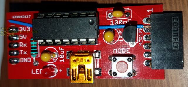 |
||||
| robert.rozee Guru Joined: 31/12/2012 Location: New ZealandPosts: 2440 |
3v3 can be picked up on one of the pins of the MCP1700 regulator. i would strongly suggest using a diode to feed the 3v3 from the regulator to pin 2 of the ICSP connector, unless someone can put forward a good reason not to? cheers, rob :-) |
||||
| Geoffg Guru Joined: 06/06/2011 Location: AustraliaPosts: 3286 |
I don't understand what the problem is. Any Micromite circuit would have its own power supply, otherwise how would it work when you are not programming the PIC32 chip? And if you are programming a bare chip (ie, no power supply) there is nothing wrong with running a jumper from the 3.3V output to your chip. What is the problem with this? Geoff Geoff Graham - http://geoffg.net |
||||
| robert.rozee Guru Joined: 31/12/2012 Location: New ZealandPosts: 2440 |
it is no problem, provided folks are aware that they need to do it. phil23 wasn't aware of it, and got stuck. the pickit2/3 has the same problem, in that by default the Vcc output is disabled, and even when enabled it often does not succeed in powering the target device. the original arduino NANO based design does supply 3v3, and so it would be nice to operate in a similar manner to be compatible. pic32prog goes to the trouble of specifically sending a command to turn on the 3v3 supply before programming, and another to turn 3v3 off after programming and verification has been completed. this was done to ensure that the target device would not run uploaded code while the programmer was still attached. i guess there is no 'perfect' answer that will suit everyone, all one can do is try to find one that creates the least number of negative user experiences. cheers, rob :-) |
||||
| Phil23 Guru Joined: 27/03/2016 Location: AustraliaPosts: 1667 |
No problem really, Just what I've personally become accustom to. I Usually just pull the backpacks (I have 4), or the E64's from their installed location, & plug them directly to the programmer & flash them. Just 1 connection required. The Backpacks always flash fine even with the display attached, & I assume the MCP1700 provides sufficient current for that. For the couple of CGMicroboards, I have a Ardruino proto board that runs a 6 pin header to the appropriate Ardruino pins. They always seem to flash happily with the display attached also. With the E100's I do remove the display, but always power is via the ICSP connector. For the couple of devices that I've built on proto boards, I just have a ZIF socket wired up for the ICSP to connect to. Phil. |
||||
| WhiteWizzard Guru Joined: 05/04/2013 Location: United KingdomPosts: 2934 |
Regarding the 'intermittent button response' issue: Rob originally suggested adding a 10K pull-up on the button input (i.e. between PIC pins 1 & 4). This had zero affect in resolving things. HOWEVER, he then suggested a 10K pull-up on the RxD pin (i.e. between Pins 1 & 5) and this has FIXED it.  As previously mentioned, when the RxD pin was left 'floating', the button response is very hit-and-miss. Now with a 10K pull-up on RxD pin it works as expected (I have removed the Pin4 pull-up by the way) As previously mentioned, when the RxD pin was left 'floating', the button response is very hit-and-miss. Now with a 10K pull-up on RxD pin it works as expected (I have removed the Pin4 pull-up by the way)ROB: can the RxD pin be pulled-up in software please? This would help avoid needing to modify the MB units I am shipping out!  WW |
||||
| matherp Guru Joined: 11/12/2012 Location: United KingdomPosts: 10273 |
No: the chip doesn't support it on the RX pin |
||||
| MicroBlocks Guru Joined: 12/05/2012 Location: ThailandPosts: 2209 |
I never had problems with the button on my version when the TX and RX pins are left floating. They are setup as a UART from the start so that should take care of the pins. This would suggest it is solvable in software. Maybe the RX pins picks up some interference which might influence the debouncing of the button. Microblocks. Build with logic. |
||||
| robert.rozee Guru Joined: 31/12/2012 Location: New ZealandPosts: 2440 |
i'm inclined to agree. but then it is perhaps not fair to expect the 1455's hardware UART to be able to handle a floating RxD pin gracefully. a good portion of the noise would translate to framing errors (a brief pulse starting a receive sequence that has an incorrect start or stop bit), and in the case of bad start bits these could be occuring at a rate far exceeding the normal character rate - such a framing error could be detected by the UART within half a bit. given that an internal pullup can not be configured, an external pullup on TxD would be my recommendation. perhaps try 47k and see if that works - though 10k is also fine. cheers, rob :-) |
||||
| MicroBlocks Guru Joined: 12/05/2012 Location: ThailandPosts: 2209 |
Even a UART getting framing errors and corrupt data, even interrupts by the UART should not influence the detection of a button press. These two 'tasks' are probably not isolated in software hence the problem with detecting the button press. If i had to make a guess it is probably a timer being used for debouncing the button that is getting reset or at least influenced by the UART giving interrupts or framing errors and that throws of the detection of the button press. Microblocks. Build with logic. |
||||
| cs41 Newbie Joined: 08/08/2016 Location: AustraliaPosts: 27 |
The problem mentioned with mains powered laptops is fairly common. Many laptops (my Toshiba included) do not have an earth connected via the mains power supply and this can produce weird effects as the laptop can be floating quite a few volts above ground. This is caused by stray capacitance from the mains to the power supply output leads. Hand capacitance to ground with devices connected via USB port can then induce voltages on floating pins and produce undesirable effects especially on high impedance or floating pins. Probably best solution if possible, is to externally ground the negative line on external equipment. This ensures (via the USB lead) that the laptop is effectively at ground potential. I have found this usually cures the problem. Hope this helps cs |
||||
| MicroBlocks Guru Joined: 12/05/2012 Location: ThailandPosts: 2209 |
@CS, i had that problem also sometimes. The solution for me was to reverse the plug. This switches the Live and Neutral wires. Always thought they were double isolated and it would not matter which way it was plugged in. I since then put a little marker on the plug and the socket to keep them the right way. Microblocks. Build with logic. |
||||
| Phil23 Guru Joined: 27/03/2016 Location: AustraliaPosts: 1667 |
That's an interesting observation, but not possible on all of my Laptop. The AU plug can't be reversed in the power point. Only 1 of their switch mode supplies has an IEC-C7, 2 pin, which is reversible, most of the others have IEC-C5, the 3 clove type, that's not reversible. Phil |
||||
| The Back Shed's forum code is written, and hosted, in Australia. | © JAQ Software 2025 |
